Nav6plus User Guide MAN 3008.00 Issue 2.0 ICS Electronics Limited. Unit V, Rudford Industrial Estate Ford, Arundel, West Sussex BN18 0BD United Kingdom Tel: +44 (0)1903 731101 Fax: +44 (0)1903 731105 E-Mail: Website: sales@icselectronics.co.uk support@icselectronics.co.uk www.icselectronics.co.uk The technical data, information and illustrations contained in this publication were to the best of our knowledge correct at the time of going to print.
Nav6 Plus Navtex System User Guide Important Information This equipment is not approved for use by SOLAS convention vessels within the Global Maritime Distress and Safety System (GMDSS) It is intended for use by leisure craft and other non-SOLAS vessels wishing to participate within GMDSS Safety Warnings Do not use the sensor as a grab-handle This instrument is for use as an aid to sailors and should not lead to a reduction in the level of good seamanship required at all times Reception of messages cannot
Nav6 Plus Navtex System User Guide Contents Quick Start...................................................................................... 5 Introduction..................................................................................... 5 Nav6plus Features.......................................................................... 6 Advanced Operation ..................................................................... 13 Navtex Mode .....................................................................
Nav6 Plus Navtex System User Guide Congratulations on purchasing this superb ICS Electronics Ltd product. It is not only an excellent Navtex receiver, but a first class instrument repeater. It may be the only display you will ever need at your navigation position. We hope that it gives you many years of reliable and trustworthy service.
Nav6 Plus Navtex System User Guide QUICK START You will find this product extremely easy to operate. Please don't be intimidated by the comprehensive nature of this manual. In reality, receiving your first NAVTEX messages just could not be simpler.
Nav6 Plus Navtex System User Guide How Does Navtex Work? NAVTEX transmissions are sent from stations situated worldwide. The power of each transmission is regulated so as to avoid the possibility of interference between transmitters. Each station is allocated a 10-minute time slot every 4 hours so that many stations can share the same frequency. Stations typically have a transmission range of 250 – 300 Nm.
Nav6 Plus Navtex System User Guide BASIC OPERATION The Nav6plus is a flexible & powerful tool for receiving, storing & viewing NAVTEX messages. In order to assist you in getting the best from your Nav6plus, read this section which contains short cuts to the most common NAVTEX operations. Read the rest of the manual for a comprehensive guide to the Nav6plus. First, find your way around the keypad and the display.
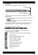
Nav6 Plus Navtex System User Guide The Display At the bottom of the display is the softkey menu area: Current option Current softkey function The softkey menu area shows what each softkey does in the current operating mode. • The top line of each softkey menu box indicates the option that is currently selected. • The bottom line of each softkey menu box indicates the current function of that softkey.
Nav6 Plus Navtex System User Guide Viewing & Scrolling Through Navtex Messages To view Navtex messages you must first select the Navtex Mode. Use the right hand softkey to change modes until ‘Navtex Mode’ is visible in the right hand softkey menu box. You can now use the UP, DOWN, LEFT & RIGHT keys to scroll through the displayed messages. UP & DOWN scroll line by line, whereas LEFT & RIGHT scroll message by message. The messages currently displayed are a sub-set of all the messages stored in memory.
Nav6 Plus Navtex System User Guide filter preset number. Select the preset that you require for the filter page that you are viewing and then look at the presets for the other filter pages. Note that the preset that is displayed is the one that is currently applied to the message display. Multiple presets can be used for switching quickly between different sets of messages on the screen.
Nav6 Plus Navtex System User Guide Automatic Station Selection Using GPS Many users will just want to display NAVTEX from the nearest NAVTEX station to their cruising location. This is most easily achieved by connecting a GPS and selecting ‘Nearest’ station option in the set up page. With a GPS connected and ‘Nearest’ selected you should only see one (or sometimes two) asterisks. Ensure that the set of stations that you want to automatically select from are all set to Auto.
Nav6 Plus Navtex System User Guide later on it is now very easy to tell if there are any new messages to read (the ‘NEW’ icon in the status bar at the top of the display will be illuminated). Note that messages that have been ‘marked as read’ will still be displayed but with the ‘NEW’ icon removed from the header in each one. However, it is possible to hide messages once they have been read.
Nav6 Plus Navtex System User Guide ADVANCED OPERATION This section provides a detailed description of the operation of your Nav6plus. The three operating modes are described in detail. Remember to use the right-hand MODE softkey to switch between the operating modes. NAVTEX MODE Navtex Mode is only available if a sensor is (or has been) connected to the display and the Navtex frequency setting on the Navtex options page is set to 518 kHz, 490 kHz or Both.
Nav6 Plus Navtex System User Guide Navtex Mode, Message View This view can be used for keeping track of new messages as they are received and displayed. Each new message can be accessed by a single key press & then marked as read, if required. The NEXT NEW softkey should be used to move the next new message to the top of the Navtex display, where it can be marked as read by pressing MARK READ. Note that the message that will be ‘marked as read’ is indicated in the top left of the status bar.
Nav6 Plus Navtex System User Guide Navtex Mode, Filter View This view allows specific stations to be selected for display and the various message categories to be turned on or off. Use the filter view to select which message types from which stations you wish to see displayed on the Navtex display. (Tip: even if you have de-selected messages from a particular station and/or message type, the system will still receive and store those messages.
Nav6 Plus Navtex System User Guide Message Categories The picture shows the 518 Types filter page; the 490 Types filter page is similar. Each of the message types can be selected as either On, Off or New Use the UP and DOWN keys to select the message type setting that you wish to edit. Use the LEFT and RIGHT keys to change the setting.
Nav6 Plus Navtex System User Guide To display messages from all stations in range of your current position, set the auto station filter to In Range. For all settings, an asterisk appears next to all stations for which messages will be displayed.
Nav6 Plus Navtex System User Guide NAVIGATE MODE Navigate Mode is only available if there is a GPS or other source of NMEA 0183 data connected to the Nav6plus NMEA input. The GPS icon in the status bar at the top of the display will be illuminated only if there is position data available on the NMEA input. There are five fixed-format Navigate data display views and four user configurable views. These can be selected from within the Navigate Mode using the VIEW softkey.
Nav6 Plus Navtex System User Guide Position View The Position View shows GPS information (Position, COG and SOG), Depth reading and Distance log using a large font. The UP, DOWN, LEFT and RIGHT keys have no function. Combined View The Combined View shows all NMEA input data on one screen using a small font. The UP, DOWN, LEFT and RIGHT keys have no function.
Nav6 Plus Navtex System User Guide Waypoint View The Waypoint View shows waypoint navigation information and a graphical “rolling road” display of the boat position and course relative to the course line. The rolling road display can be used to steer the boat along the course line whilst keeping the cross track error within chosen limits (the XTE limit may be changed on the [Setup mode⇒ ⇒Navigate View⇒ ⇒Options Page] ).
Nav6 Plus Navtex System User Guide per full feather, 50 kts per triangle. Computed Set and Drift and other related parameters are shown in digital form at the bottom of the screen. To take into account various sea states, variable damping levels may be selected by pressing the LEFT and RIGHT arrow keys. The currently selected level is shown in the top right hand corner of the display. The damping level can be None, Low, Medium or High.
Nav6 Plus Navtex System User Guide User Views The four user views can be configured to show either 2,3 or 4 panels (picture shows a 3 panel view). Each panel can be configured to show different navigation information from a range of options. See the [Setup Mode⇒ ⇒Navigate View⇒ ⇒User View Page] for more details of the available options. The UP, DOWN, LEFT and RIGHT keys have no function.
Nav6 Plus Navtex System User Guide SETUP MODE This mode enables the user to modify the operation of the Nav6plus. NAVTEX message display presentation, Navigate data presentation, LCD operation & printing operation can all be controlled from Setup Mode. Setup Mode consists of 3 ‘Views’ that can be selected with the VIEW softkey. Each View has a number of ‘Pages’ that can be selected with the PAGE softkey.
Nav6 Plus Navtex System User Guide Setup Mode, General View, Options Page Option Year Month Day Hour Minute Keyclick New Message Alert Antenna Alarm SAR Alarm Language LED Function Setting YYYY MM DD HH mm OFF ON OFF ON OFF Timed Repeated OFF Timed Repeat English Francais Portugues Deutsch OFF ON RX SAR NEW Notes Year, e.g. 2001 Month, e.g. 03 Day, e.g.
Nav6 Plus Navtex System User Guide General View Options Page This view shows general settings for the display such as Date, Time, Sound and Miscellaneous settings. Use the UP and DOWN keys to select the setting that you wish to edit. Use the LEFT and RIGHT keys to change the setting. Notes: • Date and time will be taken from NMEA input data if available.
Nav6 Plus Navtex System User Guide Option Font Error Threshold Setting Small Medium Large XX % Alphabet Latin Cyrillic Age Limit None, 1, 2, 3, 5 Days, 1, 2, 3, 4, 8, 12 Weeks None Navtex Frequency 490 kHz 518 kHz Both New Message Alert Antenna Alarm SAR Alarm Display Mode Off On Off Timed Repeat Off Timed Repeat Master Slave Notes Display Navtex messages using small font Display Navtex messages using medium font Display Navtex messages using large font Percentage character error rate above wh
Nav6 Plus Navtex System User Guide Option Auto Print Setting Off On Manual Print Off On Output Format Data Printer Antenna Type Firmware Version Hardware Revision Switchable Dual X.X X Notes Auto printing off Auto printing on. New messages will be printed when received. The print filter settings can be used to filter which messages are printed based upon message type and station Manual printing off. The Navtex Mode, Print View is hidden Manual printing on.
Nav6 Plus Navtex System User Guide The picture shows the 490 Types filter page; the 518 Types filter page is similar. Each of the message types can be selected as either ON or OFF. Use the UP and DOWN keys to select the message type setting that you wish to edit. Use the LEFT and RIGHT keys to change the setting. The picture shows the 518 Stations filter page; the 490 Stations filter page is similar. Use the UP and DOWN keys to select the station filter setting that you wish to edit.
Nav6 Plus Navtex System User Guide Set the filter for each station to one of the following: Setting On Off Auto Notes Messages from station always printed Messages from station never printed Messages from station printed only when nearest or in range depending upon setting. Setup Mode, Navtex View, 518 and 490 Names Pages The station names setup pages determine the names of stations displayed on station filter pages and in Navtex message headers.
Nav6 Plus Navtex System User Guide Setup Mode, Navtex View, 518 and 490 Names, Station Database Setup Press the STATION DATABASE softkey from within the [Setup Mode⇒ ⇒Navtex View⇒ ⇒518 or 490 Names Page] to display the station database setup page for 518 or 490 kHz. Press the EXIT softkey to leave the station database setup. The station database page is divided into two halves. The top half shows a scrolling list of all stations in the database.
Nav6 Plus Navtex System User Guide When you have finished entering the data, press the SAVE softkey to save and update the database or CANCEL softkey to abort the change. Field Station Area Name Notes The station letter: A to X The Nav-Area: I to XVI The station name as displayed on Navtex messages. Up to 17 characters. Latitude The transmitter position. Used to determine the Longitude nearest and in-range stations Range The stated coverage range of the station in NM. Used to determine in range stations.
Nav6 Plus Navtex System User Guide Setup Mode, Navtex View, Monitor Page The monitor page shows a split screen view of live 490 and 518 kHz transmissions as they are received. None of the filtering selected in the various setup pages is applied. The monitor page displays ALL incoming data regardless of error rate. The monitor page also shows the low level phasing characters contained within transmissions (shown as ø characters) and transmission errors (shown as ✸characters).
Nav6 Plus Navtex System User Guide Option Distance Units Speed Units Depth Units North Reference Setting NM km mi Kt Km/h m/s mph ft m True Magnetic Heading Reference True Magnetic Wind Speed Units Wind Reference Kt Km/h m/s mph True Relative Damping None, Low, Medium, High Demo Mode Off On XTE Limit 0.
Nav6 Plus Navtex System User Guide Option Manual Print Setting Off Notes Manual printing off. The Print softkey on the Navigate Mode, Log View is hidden Manual printing on.
Nav6 Plus Navtex System User Guide Option Format Setting Off 2 Panels Notes Disable the user view page Display the user view page with two large panels. Display the user view page with one large panel at the top and two small panels at the bottom. Display the user view page with four small panels.
Nav6 Plus Navtex System User Guide ALARM OPERATION The Nav6 display contains a buzzer that can generate audible alarms for the following conditions: Option New Message Alert Notes Short beep beep. Not repeated. Indicates reception of a new Navtex message. SAR Alarm Morse code: Dot dot dot, dash dash dash, dot dot dot.. Repeated every ten seconds. Indicates reception of a message type D, Search And Rescue Navtex message. Antenna Alarm Short dah dee, dah dee. Repeated every eight seconds.
Nav6 Plus Navtex System User Guide PRINTING NAVTEX AND NAVIGATION LOG The Nav6plus can be configured to function like a GMDSS paper Navtex printer when connected to a suitable serial printer. A Nav6 serial printer can be purchased from ICS (ICS order number 918.00). Alternatively, an ICS Nav4 Navtex receiver can be modified to become a Nav6 serial printer by purchasing a Nav4 to Nav6 printer conversion kit (ICS order number 6100.00).
Nav6 Plus Navtex System User Guide • • • Setup the Navtex print filtering to select which message types from which stations should be printed; see Setup Mode⇒ ⇒Navtex View⇒ ⇒Options Page⇒ ⇒Print Setup. Enable Navigate auto print and set the logging interval; see Setup Mode⇒ ⇒Navigate View⇒ ⇒Options Page. Enable Navigate manual print if you want to be able to print the current page of log entries from the navigation log using the PRINT softkey on the Navigate Mode⇒ ⇒Log View.
Nav6 Plus Navtex System User Guide etc. • On a yacht, pushpit mounting is permissible. Note: due to the variety of possible mounting methods (horizontal rail, vertical rail, deck, etc) ICS do not supply the antenna mounting bracket as standard. They are readily available from most marine electronics stores. Mounting the Sensor Unit • • First, fix the antenna mount in the desired location.
Nav6 Plus Navtex System User Guide Twisted Pair Core Colour Signal description YELLOW twisted with BLACK YELLOW BLACK POWER from display GND from display WHITE twisted with BLACK WHITE BLACK DATA A from display DATA B from display Screen Silver Screen (nominally 0V) Routing of the Sensor Cable The Sensor Cable should be connected to the Display Unit via the terminal strip supplied. • The Sensor Cable should be routed to the Display Unit taking care that potential tripping hazards are avoided.
Nav6 Plus Navtex System User Guide INSTALLATION OF DISPLAY UNIT • Choose a location that is flat, free from excessive heat and vibration, and which is convenient for routing the Display Cable. The display is best viewed when the screen is mounted square on. • The Display Unit has been designed for above or below decks mounting.
Nav6 Plus Navtex System User Guide Nav4 to Nav6 Conversion Mounting Plate Please follow the fitting instructions contained within the optional Nav4 to Nav6 Conversion Mounting Plate kit.
Nav6 Plus Navtex System User Guide The following diagram shows a typical Nav6 system. Na vt e x NAV-6 ANTENNA ICS WHITE WHITE BLACK BLACK YELLOW YELLOW BLACK BLACK SCREEN DRAIN SCREEN DRAIN GREEN BATTERY GPS SENSOR +12v RED GND BLACK NAV-6 DISPLAY BLUE A BLACK B NAV-6 PRINTER BLACK * TX BROWN RX BLACK NAV6 Printer * Not connected Connecting Power The Nav6 Navtex System should be powered from a nominal 12Vdc switched supply, capable of providing a continuous 350mA.
Nav6 Plus Navtex System User Guide Connecting the Sensor • Connect the sensor power. Connect the YELLOW and BLACK twisted pair from the display to the YELLOW and BLACK twisted pair of the sensor; YELLOW to YELLOW, BLACK to BLACK. • Connect the sensor data. Connect the WHITE and BLACK twisted pair from the display to the WHITE and BLACK twisted pair of the sensor; WHITE to WHITE, BLACK to BLACK. • Connect the screen. Connect the silver screen wires of the display and sensor.
Nav6 Plus Navtex System User Guide Connecting an NMEA Source • Use the BLUE and BLACK twisted pair for connection to the NMEA data source. • Connect the BLUE wire to the NMEA A signal. • Connect the BLACK wire to the NMEA B signal.
Nav6 Plus Navtex System User Guide Connecting a PC, Printer or Plotter The following equipment with RS232 serial data connection may be connected to the Nav6: • A PC (via ICS Cable option 6020.09). • Or a printer or chart plotter (via ICS Cable option 6020.10). The PC and printer serial port should be set to 4800 baud, 8 data bits, no parity, 1 stop bit, and no flow control. A terminal emulator program, such as HyperTerminal, can be used to monitor the data output.
Nav6 Plus Navtex System User Guide Connecting Multiple Display Units Where multiple displays are required, these may be purchased as an option (ICS part number 6003.00). In addition, a Nav6 hub is required to interconnect the equipment (ICS part number 919.00). For full details on using the Nav6hub within an extended Nav6 system, please refer to the Nav6hub User Guide.
Nav6 Plus Navtex System User Guide TESTING THE NAV6 AFTER INSTALLATION • • Carefully check all connections before applying power. Switch on the power supply by closing the 1.5A circuit breaker or power panel switch. • Check that the red LED illuminates for approximately 8 seconds and then goes out and the start-up page appears on the Nav6 display. The start-up progress bar at the bottom of the page will disappear when the system is ready to use. Press any key to show the next screen.
Nav6 Plus Navtex System User Guide Fault Finding Fault Possible cause LCD blank, RED LED On Green wire connected to 12V Disconnect green wire – it should not be connected other than for programming No power Check that 12V is connected to RED wire and 0V to its BLACK pair Low voltage There is insufficient voltage supplying the display Sleep Mode Press any key to activate the display LCD blank, RED LED off RED LED flashing with a period of 2 seconds. Display not operating.
Nav6 Plus Navtex System User Guide Software Upgrade The Nav6plus has FLASH memory based software. This allows the Nav6plus to be upgraded when new software releases are developed. Please check our website www.icselectronics.co.uk for information on new releases. Input Fuse The Nav6plus has a built-in resettable fuse on its 12V input. This fuse will trip if the unit due to a fault condition draws excessive currents. Power must be disconnected from the unit for 10 seconds in order for the fuse to reset.
Nav6 Plus Navtex System User Guide GLOSSARY COG GMDSS IMO NMEA RS485 RS232 SAR SOG SOLAS TTG XTE Course Over Ground Global Maritime Distress and Safety System International Maritime Organisation National Marine Electronics Association Serial data communication interface Serial data communication interface Search and Rescue Speed Over Ground Safety of Life at Sea Time To Go Cross Track Error PACKING LIST AND OPTIONS Packing List For the Nav6 System contents – please see the packing list enclosed.
Nav6 Plus Navtex System User Guide SPECIFICATION Approval Standards Meets the EMC requirements of IEC 60945 Power Voltage range 10.8V to 15.6V Consumption (Typical) Backlight full 310 mA (3.8 W at 12V) Backlight off 165 mA (2.0 W at 12V) Sleep mode 115 mA (1.4 W at 12V) Display Unit Operating Temperature Range 0 to +50degC Storage Temperature Range -20 to +55degC Humidity 0 to 95% Mounting Above or below decks Weight (without cable) 445 g (approx.) Power 10.8V to 15.
Nav6 Plus Navtex System User Guide Display Unit Features 1/2vga (480x320 pixels) monochrome LCD with 4 grey levels 32 step CCFL backlighting of LCD 128 step contrast adjustment of LCD LED backlighting for keyboard RS485 serial I/O port to sensor NMEA input RS232 printer output Piezo buzzer for audible alarms Internal temperature sensor Non volatile memory 53
Nav6 Plus Navtex System User Guide APPENDIX I: NAVTEX STATION DATABASE 518kHz Navtex Stations Id A A A A A A A A B B B B B B B B C C C C C C C C C D D D D D D D D E E E E E F F F F F F F F F G G G G G G G H H H H Area 01 02 03 04 09 11 13 15 01 03 04 07 09 11 13 15 01 03 04 07 08 11 12 13 15 01 02 03 04 11 12 13 15 03 11 12 13 15 01 02 03 04 06 09 11 13 15 01 02 04 08 09 11 15 01 03 04 06 Country Norway France Russia USA Iran Indonesia Russia Chile Norway Ukraine Bermuda Namibia Bahrain Indonesia Russia
Nav6 Plus Navtex System User Guide Id H H H H I I I I I J J J J J J K K K L L L L M M M M M M N N N N N O O O O O O O P P P P P P P P P P P Q Q Q Q Q Q R R R R R R R S Area 09 11 12 15 02 03 07 11 15 01 03 04 11 12 15 01 03 11 01 03 11 15 01 02 03 06 09 11 01 03 04 06 11 01 03 04 06 07 11 12 01 03 04 06 08 09 11 11 11 11 11 01 03 04 06 11 12 01 02 03 04 06 11 12 01 Country Saudi Arabia Japan Canada Chile Islas Canarias Turkey South Africa Japan Chile Sweden Bulgaria Canada Japan Alaska Chile UK Greece Jap
Nav6 Plus Navtex System User Guide Id S S S T T T T U U U U U V V V V V W W W W W W W X X X X X Area 04 11 16 01 03 04 11 01 03 04 11 16 01 03 04 11 11 01 03 04 11 11 12 16 03 04 09 11 12 Country Canada Malaysia Peru Belgium Italy Canada Malaysia Estonia Italy Canada Malaysia Peru Norway Italy Canada South Korea Mariana Islands Ireland France Greenland Vietnam South Korea USA Peru Spain Canada Egypt Vietnam Alaska Name Iqaluit Labuan Paita Oostende Cagliari Iqaluit Kuching Tallinn Trieste Fundy Port Kela
Nav6 Plus Navtex System User Guide APPENDIX II: MESSAGE TYPE INDICATORS Navtex broadcasts use following message type letter: A B C D E F G H I J L V W X Y Z Navigational warnings Meteorological warnings Ice reports Search and rescue information, and pirate warnings Meteorological forecasts Pilot service messages DECCA messages LORAN messages OMEGA messages (Note: OMEGA has been discontinued) SATNAV messages (i.e. GPS or GLONASS) Navigational warnings - additional to letter A Notice to Fishermen (U.S.
Nav6 Plus Navtex System User Guide APPENDIX IV: NAV6 MENU NAVIGATION 4 3 2 FUNCTION Mark Read PAGE Next New VIEW Message View Print Next New Print View Date Criteria Ascending Order Station Criteria Type Criteria 4 Descending Order MODE 2 2 3 Sort View 4 Preset 1 Navtex Mode 2 490 Types Page Preset 2 4 Preset 3 4 Preset 4 4 Preset 5 4 1 490 Stns Page 518 Types Page 518 Stns Page 3 3 Filter View 3 1 Position View Combined View 2 Waypoint View 2 Conning View 2 User
Nav6 Plus Navtex System User Guide APPENDIX V: NAV6 MENU STRUCTURE Navtex - Mode 1 Message - View Print - View Notes: Next New Mark read 2 Next new Print Sort - View Order Ascending Descending Criteria Date Station Type 1. Receiver type selection, controls whether this option is displayed. 2. Only displayed if manual Navtex printing ON 3. Only displayed if manual navigate log printing ON 4. Only displayed if the station database memory is full 5.
Nav6 Plus Navtex System User Guide 60