
User guide


Nav6 Plus Navtex System User Guide
43
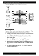
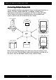
The following diagram shows a typical Nav6 system.
WHITE
BLACK
YELLOW
BLACK
WHITE
BLACK
YELLOW
BLACK
ICS
Navtex
RED
BLACK
+12v
GND
BROWN
BLACK
GREEN
BLACK *
BLUE
BLACK
SCREEN DRAIN
SCREEN DRAIN
BATTERY
NAV-6
DISPLAY
NAV-6 ANTENNA
A
B
GPS
SENSOR
TX
RX
NAV-6 PRINTER
NAV6 Printer
* Not connected
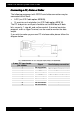
Connecting Power
Connecting PowerConnecting Power
Connecting Power
The Nav6 Navtex System should be powered from a nominal 12Vdc
switched supply, capable of providing a continuous 350mA.
• To allow the unit to be isolated for service, a 1.5A circuit breaker
or a 1.5A fuse and switch should switch the power supply.
• Use the RED and BLACK twisted pair for connection to the
boat’s power supply.
• Connect the RED wire to boat’s positive (12V) supply.
• Connect the BLACK wire to negative (0V) supply.
• Note that vessels that require isolation may need to install a DC
to DC converter (ICS part number 500.09) – if in doubt ask your
dealer.
• 24V vessels should install the 24V / 12V DC to DC converter
(ICS part number 500.10).