Installation and Maintenance Manual IMM ACZ/AGZ-4 Group: Chiller Part Number: 331374201 Effective: October 2006 Supersedes: August 2006 Air-Cooled Scroll Condensing Units ACZ 030B through 155B Air-Cooled Scroll Chillers w/ Remote Evaporators AGZ 026BM through 130BM 60 Hertz, R-22, R 407C
Table of Contents Introduction.................................................... 3 General Description.....................................................3 Inspection ....................................................................3 Nomenclature ..............................................................3 Installation...................................................... 4 Handling ......................................................................4 Location....................................
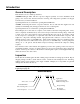
Introduction General Description This manual covers two similar product lines: AGZ-BM, Packaged chiller with the evaporator shipped separately for remote installation, field piping to the outdoor unit, and interconnection of wiring. The refrigeration specialties are shipped from the factory for field installation. Operating instructions are contained in operating manual OM AGZ. ACZ-BC, Condensing unit with no evaporator included.
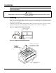
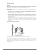
Installation Note: Installation is to be performed by qualified personnel who are familiar with local codes and regulations. WARNING Sharp edges on unit and coil surfaces are a potential hazard to personal safety. Avoid contact with them. Handling Be careful to avoid rough handling of the unit. Do not push or pull the unit from anything other than the base. Block the pushing vehicle away from the unit to prevent damage to the sheet metal cabinet and end frame (see Figure 1).
Location Figure 3, Clearances Unit Placement ACZ/AGZ units are for outdoor applications and can be mounted either on a roof or at ground level. For roof mounted applications, install the unit on a steel channel or I-beam frame to support the unit above the roof. For ground level applications, install the unit on a substantial base that will not settle. A one-piece concrete slab with footings extended below the frost line is recommended.
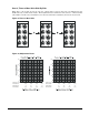
Restricted Air Flow General The clearances required for design-life operation of ACZ/AGZ air-cooled units are described in the previous section. Occasionally, these clearances cannot be maintained due to site restrictions, such as units being too close together, or a fence or wall restricting airflow, or both. The McQuay ACZ/AGZ units have several features that can mitigate the problems attributable to restricted airflow. • The condenser section is configured as shown below.
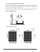
Case 1, Building or Wall on One Side of One Unit The existence of a screening wall, or the wall of a building, in close proximity to an air-cooled unit is common in both rooftop and ground level applications. Hot air recirculation on the coils adjoining the wall will increase compressor discharge pressure, decreasing capacity and increasing power consumption. Only the compressor(s) connected to these coils will be affected. When close to a wall, place chillers on the north or east-side of them.
Case 2, Two Units Side By Side Two or more units sited side by side are common. If spaced closer than 12 feet (3.7 meters), or 8 feet (2.5meters), depending on size, it is necessary to adjust the performance of each unit. Circuits adjoining each other are affected. NOTE: This case applies only to two units side by side. See Case 3 for three or more parallel units. If one of the two units also has a wall adjoining it, see Case 1.
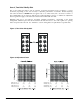
Case 3, Three or More Units Side By Side When three or more units are side by side, the outside units (1 and 3 in this case) are influenced by the middle unit only on their inside circuits. Their adjustment factors will be the same as Case 2. All inside units (only number 2 in this case) are influenced on both sides and must be adjusted by the factors shown below. Figure 9, Three or More Units Chiller 1 Chiller 2 Chiller 3 Figure 10, Adjustment Factor 4.0 8.0 3.0 6.0 2.0 4.0 1.0 2.
Case 4, Open Screening Walls Decorative screening walls are often used to help conceal a unit either on grade or on a rooftop. These walls should be designed such that the combination of their open area and distance from the unit do not require performance adjustment. It is assumed that the wall height is equal to or less than the unit height when mounted on its base support. This is usually satisfactory for concealment. If the wall height is greater than the unit height, see Case 5, Pit Installation.
Case 5, Pit/Solid Wall Installation Pit installations can cause operating problems and great care should be exercised if they are to be used on an installation. Recirculation and restriction can both occur. A solid wall surrounding a unit is substantially the same as a pit and the data presented here should be used. Steel grating is sometimes used to cover a pit to prevent accidental falls or trips into the pit.
Sound Isolation The low sound level of the ACZ/AGZ units is suitable for most applications. When additional sound reduction is necessary, locate the unit away from sound sensitive areas. Avoid locations beneath windows, or between structures where normal operating sounds can be objectionable. Reduce structurally transmitted sound by isolating refrigerant lines, electrical conduit and the unit itself.
Table 2, Isolator Loads At Each Mounting Location (With Aluminum Fins) ACZ-B Model AGZ-BM Model ACZ 030 AGZ 026 ACZ 035 AGZ 030 ACZ 040 AGZ 035 ACZ 045 AGZ 040 ACZ 050 AGZ 045 ACZ 055 AGZ 050 ACZ 060 AGZ 055 ACZ 065 ACZ 070 ACZ 080 AGZ 060 AGZ 065 AGZ 070 Shipping Wt Operating. Wt Loc. 1 Loc.
Table 5, Isolator Locations ACZ-BS, AGZ-BM Less Evaporator Units ACZ- AGZBS BM Model Model Operating Weight lbs kg Neoprene-In-Shear Mountings 1 2 3 4 Spring-Flex Mountings 5 6 1 2 3 4 (1) 5 6 - - 030 026 3600 1631 Black Gray Gray Green - - Orange Purple Red Orange 035 030 3600 1631 Black Gray Gray Green - - Orange Purple Red Orange 040 035 3600 1631 Black Gray Gray Green - - Orange Purple Red Orange - - 045 040 3610 1635 Black Gray Gray Green
1. Vibration eliminators to reduce vibration and noise transmission to the building. 2. Shutoff valves are required to isolate the unit from the piping system during unit servicing. 3. Manual or automatic air vent valves at the high points of the system. Drains must be installed at the lowest points in the system. 4. Adequate system water pressure must be maintained (expansion tank or regulating valve). 5. Temperature and pressure indicators located at the unit are required to aid in unit servicing. 6.
Figure 18, AGZ 026BM - AGZ 070BM, Typical Field Evaporator Water Piping T Air Vent Strainer Inlet Isolation Valves Vibration Eliminators P Outlet Flow Switch T Thermowell Drain Flow Switch (Model AGZ-BM) Mount a water flow switch in the leaving water line of the remote water chiller to shut down the unit when water flow is interrupted. A flow switch is an equipment protection control and should never be used to cycle a unit. A flow switch is available from McQuay (part number 017503300).
Variable Speed Pumping Variable water flow involves lowering the water flow through the evaporator as the load decreases. McQuay chillers are designed for this duty provided that the rate of change in water flow is slow and the minimum and maximum flow rates for the vessel are not exceeded. The recommended maximum change in water flow is 10 percent of the change per minute. The water flow through the vessel must remain between the minimum and maximum values listed on page 25.
CAUTION Do not use an automotive grade antifreeze. Industrial grade glycols must be used. Automotive antifreeze contains inhibitors which will cause plating on the copper tubes within the chiller evaporator. The type and handling of glycol used must be consistent with local codes. Table 8, Ethylene Glycol Factors for Models AGZ 026BM to 070BM % E.G. 10 20 30 40 50 Freeze Point o F 26 18 7 -7 -28 o C -3.3 -7.8 -13.9 -21.7 -33.3 Capacity Power Flow PD 0.998 0.993 0.987 0.980 0.973 0.998 0.997 0.
Evaporator Temperature Drop Factors Performance tables are based on a 10 degree F (5 degree C) temperature drop through the evaporator. Adjustment factors for applications with temperature ranges from 6 degree F to 16 degree F (3.3 degree C to 8.9 degree C) are found in Table 12 and Table 13. Ranges outside these temperatures can affect the control system's capability to maintain acceptable control and must not be used.
Table 13, Capacity and Power Derates, Models AGZ 075 to 130 Altitude Sea Level 2000 feet 4000 feet 6000 feet 8000 feet 20 Fouling Factor Chilled Water Delta T 0.0001 (0.0176) 0.00025 (0.044) 0.00075 (0.132) 0.00175 (0.308) °F °C Cap. Power Cap. Power Cap. Power Cap. Power 6 3.3 0.990 0.997 0.976 0.994 0.937 0.983 0.868 0.964 8 4.4 0.994 0.998 0.981 0.995 0.942 0.984 0.872 0.965 10 5.6 1.000 1.000 0.987 0.996 0.947 0.986 0.877 0.967 12 6.7 1.005 1.
ACZ Staging and Circuiting All ACZ units have two circuits, each with either two compressors, or three compressors on models ACZ 120 through 155. These circuits must be kept separated throughout the entire refrigerant piping system. Each unit refrigerant circuit must be piped to a separate coil or to a separate air handler (with a single coil). Temperature control for each evaporator coil is provided by the installer through field-supplied and wired temperature controllers.
Remote Evaporator Refrigerant Piping Figure 20, AGZ-BM, Remote Evaporator Piping Schematic Refrigerant Specialties: AGZ-BM Remote Evaporator Chillers: Refrigerant specialties including the expansion valves, solenoid valves, filter-drier and sight glasses for use with the AGZ-BM remote evaporator models are supplied by McQuay but require field installation. The remaining components including fittings and Schrader valves are provided and piped by the installer.
Refrigerant Piping All field piping, wiring, and procedures must be performed in accordance with ASHRAE, EPA, and industry standards. Proper refrigerant piping can make the difference between a reliable system and an inefficient, problematic system. The primary concerns related to piping are refrigerant pressure drop, a solid liquid feed to the expansion valves, continuous oil return and properly sized refrigerant specialties. Insulate the suction line to reduce excessive superheat build-up.
Chilled Water Flow Switch A water flow switch must be mounted in the leaving chilled water line to prove that there is adequate water flow to the evaporator before the unit can start. It also serves to shut down the unit in the event that water flow is interrupted in order to guard against evaporator freeze-up. A flow switch is available from McQuay under ordering number 017503300. It is a paddle-type switch and adaptable to any pipe size from 1" (25mm) to 8" (203mm) nominal.
Evaporator Flow and Pressure Drop Figure 21, AGZ 026BM – 130BM, Remote Evaporator Pressure Drop 075-085-090 120-130 026-030 035 040 050 045 AGZ Unit Model 026B 030B 035B 040B 045B 050B 055B 060B 065B 070B 075B 085B 090B 100B 110B 120B 130B 060 100-110 065-070 055 Minimum Inch-Pound S.I. gpm DP ft. lps DP kpa 41 1.6 2.6 4.7 45 1.9 2.9 5.7 50 1.9 3.1 5.6 58 1.9 3.6 5.7 64 1.8 4.0 5.4 71 1.8 4.4 5.4 78 1.8 4.9 5.3 86 1.7 5.4 5.2 92 1.6 5.8 4.9 98 1.9 6.2 5.6 111 5.6 7.0 16.5 119 6.3 7.5 18.9 128 7.
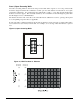
Wind Baffles and Hail Guards Wind Baffles/Hail Guards are a field-installed option that is used to stabilize unit operation in high wind areas and to assist in operation at low ambient temperatures. Figure 22 is a sketch of a typical panel assembly on an ACZ/AGZ unit. The actual number of panels and parts will vary by model size. The parts are shown in the table below and referenced by balloon numbers.
Vertical Support Rib Top Cover Front Panel ¼ - 20 x ½” Screw (Place in Poly Bag) 074758501 330409401 330409501 046093807 1 2 3 Figure 23, Components TOP REAR (AGAINST UNIT) VERTICAL SUPPORT RIB TOP COVER FRONT PANEL Top Panel, Install Last Overlap the Front panel Front Panel, Install Second Rib, Install First IMM ACZ/AGZ-4 ACZ / AGZ-BM 27
Physical Data Table 16, ACZ 030B - 040B, AGZ 026BM – 035BM PHYSICAL DATA ACZ 030B, AGZ 026BM BASIC DATA Ckt.1 Ckt.2 Number Of Refrigerant Circuits MODEL NUMBER ACZ 035B AGZ 030BM Ckt.1 Ckt.2 2 ACZ 040B AGZ 035BM Ckt.1 Ckt.2 2 2 Unit Operating Charge, R-22, Lbs. 22 22 22 27 27 27 Unit Operating Charge, R-22, kg 10 10 10 12 12 12 Cabinet Dimensions, LxWxH, In. 94.4 x 88.0 x 100.4 94.4 x 88.0 x 100.4 94.4 x 88.0 x 100.
Table 17, ACZ 045B - 060B, AGZ 040BM – 055BM PHYSICAL DATA BASIC DATA MODEL NUMBER ACZ 050B ACZ 055B AGZ 045BM AGZ 050BM ACZ 045B AGZ 040BM Ckt.1 Number Of Refrigerant Circuits Ckt.1 Ckt.2 2 Unit Operating Charge, R-22, lbs. Unit Operating Charge, R-22, kg Cabinet Dimensions, LxWxH, in. Cabinet Dimensions, LxWxH, (mm) Unit Operating Weight, Lbs. (kg) Ckt.1 Ckt.2 Ckt.1 2 ACZ 060B AGZ 055BM Ckt.2 2 Ckt.2 2 31 31 37 37 37 37 44 44 14 14 17 17 17 17 20 20 94.4 x 88.0 x 100.4 94.
Table 18, ACZ 065B - 080B, AGZ 060BM – 070BM PHYSICAL DATA ACZ 065B AGZ 060BM BASIC DATA Ckt.1 Number Of Refrigerant Circuits Ckt.2 MODEL NUMBER ACZ 070B AGZ 065BM Ckt.1 2 Unit Operating Charge, R-22, lbs. Unit Operating Charge, R-22, kg Cabinet Dimensions, LxWxH, in. Ckt.2 ACZ 080B AGZ 070BM Ckt.1 Ckt.2 2 2 44 44 50 57 57 57 20 20 23 26 26 26 94.4 x 88.0 x 100.4 94.4 x 88.0 x 100.4 94.4 x 88.0 x 100.
Table 19, ACZ 090B - 110B, AGZ 075BM – 090BM PHYSICAL DATA ACZ 090B AGZ 075BM Ckt.1 Ckt.2 2 56 56 25 25 134.9 x 88.0 x 100.4 3426 x 2235 x 2550 5630 (2556) 5510 (2502) 870 (395) MODEL NUMBER ACZ 100B AGZ 085BM Ckt.1 Ckt.2 2 56 66 25 30 134.9 x 88.0 x 100.4 3426 x 2235 x 2550 5790 (2629) 5670 (2574) 870 (395) ACZ 110B AGZ 090BM Ckt.1 Ckt.2 2 66 66 30 30 134.9 x 88.0 x 100.4 3426 x 2235 x 2550 5950 (2701) 5830 (2647) 870 (395) 1 2 14.0 x 5.2 356 x 1585 25 (95) 152 (1047) 300 (2066) 5 (127) 0.5 (12.7) 0.
Table 20, ACZ 120B - 155B, AGZ 100BM – 130BM PHYSICAL DATA ACZ 120B AGZ 100BM Ckt.1 Ckt.2 2 72 82 33 37 173.1 x 88.0 x 100.4 4397 x 2235 x 2550 6970 (3164 6820 (3096) 1155 (524) MODEL NUMBER ACZ 130B ACZ 140B AGZ 110BM AGZ 120BM Ckt.1 Ckt.2 Ckt.1 Ckt.2 2 2 82 82 82 99 37 37 37 45 173.1 x 88.0 x 100.4 173.1 x 88.0 x 100.4 4397 x 2235 x 2550 4397 x 2235 x 2550 7230 (3282) 7480 (3396) 7080 (3214) 7360 (3341) 1155 (524) 1155 (524) BASIC DATA Number Of Refrigerant Circuits Unit Operating Charge, R-22, lbs.
Electrical Data Standard Ambient Table 21, ACZ BC & AGZ BM Electrical Data, Single Point (105°F & below) ACZ Unit Size AGZ Unit Size 030B 026B 035B 030B 040B 035B 045B 040B 050B 045B 055B 050B 060B 055B 065B 060B 070B 065B 080B 070B Volts Minimum Circuit Ampacity (MCA) 208 230 380 460 575 208 230 380 460 575 208 230 380 460 575 208 230 380 460 575 208 230 380 460 575 208 230 380 460 575 208 230 380 460 575 208 230 380 460 575 208 230 380 460 575 208 230 380 460 575 133 126 80 68 52
Table 22, ACZ BC & AGZ BM Compressor & Fan Motor Amps, Single & Multi-Point (Up to 105°F) ACZ Unit Size AGZ Unit Size Rated Load Amps Compressors Volts No. 1 No. 3 No. 2 208 25.7 25.7 230 24.2 24.2 14.9 14.9 030B 026B 380 460 13.4 13.4 575 9.3 9.3 208 25.7 25.7 230 24.2 24.2 14.9 14.9 035B 030B 380 460 13.4 13.4 575 9.3 9.3 208 31.8 31.8 230 29.9 29.9 18.6 18.6 040B 035B 380 460 16.0 16.0 575 12.2 12.2 208 33.8 33.8 230 33.8 33.8 22.8 22.8 045B 040B 380 460 16.5 16.5 575 13.7 13.7 208 33.8 33.8 230 33.
Table 23, ACZ BC & AGZ BM Field Wiring, Single Point ACZ Unit Size AGZ Unit Size 030B 026B 035B 030B 040B 035B 045B 040B 050B 045B 055B 050B 060B 055B 065B 060B 070B 065B 080B 070B All Electrical Data IMM ACZ/AGZ-4 Wiring to Standard Power Block Volts Terminal Amps 208 175 230 175 380 175 460 175 575 175 208 380 230 380 380 175 460 175 575 175 208 380 230 380 380 175 460 175 575 175 208 380 230 380 380 175 460 175 575 175 208 380 230 380 380 175 460 175 575 175 208 380 230 380 380
Table 24, ACZ BC & AGZ BM Electrical Wiring, Single Point (Up to 105°F) ACZ Unit Size AGZ Unit Size 090B 075B 100B 085B 110B 090B 120B 100B 130B 110B 140B 120B 155B 130B Volts Minimum Circuit Ampacity (MCA) 208 230 380 460 575 208 230 380 460 575 208 230 380 460 575 208 230 380 460 575 208 230 380 460 575 208 230 380 460 575 208 230 380 460 575 358 358 187 150 125 380 380 219 171 136 414 414 248 188 146 463 463 260 199 171 528 528 282 220 182 613 613 323 248 198 613 613 361 273 212 Power
Table 25, ACZ BC & AGZ BM Compressor and Fan Motor Amps, Single and Multi-Point (Up to 105°F) ACZ Unit Size AGZ Unit Size Rated Load Amps Compressors Volts No. 1 No. 3 No. 5 No. 2 No. 4 No. 6 208 73.1 73.1 230 73.1 73.1 090B 075B 380 38.2 38.2 460 30.1 30.1 575 25.2 25.2 208 73.1 73.1 230 73.1 73.1 100B 085B 380 38.2 38.2 460 30.1 30.1 575 25.2 25.2 208 86.4 86.4 230 86.4 86.4 110B 090B 380 52.5 52.5 460 39.0 39.0 575 30.0 30.0 208 52.8 52.8 230 52.8 52.8 120B 100B 380 32.7 32.7 460 23.7 23.7 575 21.
Table 26, ACZ BC & AGZ BM Field Wiring, Single Point ACZ Unit Size AGZ Unit Size 090B 075B 100B 085B 110B 090B 120B 100B 130B 110B 140B 120B 155B 130B All Electrical Data 38 Wiring to Standard Power Block Volts Terminal Amps 208 760 230 760 380 380 460 380 575 380 208 760 230 760 380 380 460 380 575 380 208 760 230 760 380 380 460 380 575 380 208 760 230 760 380 380 460 380 575 380 208 760 230 760 380 380 460 380 575 380 208 760 230 760 380 380 460 380 575 380 208 760 230 760 380 760 460
Table 27, ACZ BC & AGZ BM Electrical Data, Multi-Point (Up to 105°F) ACZ Unit Size AGZ Unit Size 030B 026B 035B 030B 040B 035B 045B 040B 050B 045B 055B 050B 060B 055B 065B 060B 070B 065B 080B 070B Volts 208 230 380 460 575 208 230 380 460 575 208 230 380 460 575 208 230 380 460 575 208 230 380 460 575 208 230 380 460 575 208 230 380 460 575 208 230 380 460 575 208 230 380 460 575 208 230 380 460 575 Electrical Circuit #1 Electrical Circuit #2 Recomm’d Power Supply Power Supply Recomm’d Minimum
Table 28, ACZ BC & AGZ BM Field Wiring, Multi-Point ACZ Unit Size AGZ Unit Size Wiring to Standard Power Block Volts Terminal Amps Cir #1 Cir #2 208 175 175 230 175 175 380 175 175 030B 026B 460 175 175 575 175 175 208 175 175 230 175 175 380 175 175 035B 030B 460 175 175 575 175 175 208 175 175 230 175 175 380 175 175 040B 035B 460 175 175 575 175 175 208 175 175 230 175 175 380 175 175 045B 040B 460 175 175 575 175 175 208 175 175 230 175 175 380 175 175 050B 045B 460 175 175 575 175 175 208 175 175 2
Table 29, ACZ BC & AGZ BM Field Wiring Data ACZ Unit Size AGZ Unit Size Wiring to Standard Power Block Volts Terminal Amps Cir #1 Cir #2 208 380 380 230 380 380 380 175 175 090B 075B 460 175 175 575 175 175 208 380 380 230 380 380 380 175 175 100B 085B 460 175 175 575 175 175 208 380 380 230 380 380 380 175 175 110B 090B 460 175 175 575 175 175 208 380 380 230 380 380 380 175 175 120B 100B 460 175 175 575 175 175 208 380 380 230 380 380 380 380 380 130B 110B 460 380 380 575 175 175 208 380 380 230 380 3
Table 30, ACZ BC & AGZ BM Electrical Data, Multi-Point (Up to 105°F) Electrical Circuit #1 Electrical Circuit #2 Power Power Recomm’d Recomm’d Max. Supply Supply Minimum Max.
Electrical Data High Ambient Table 31, ACZ BC & AGZ BM Electrical Data, Single Point ACZ Unit Size AGZ Unit Size 030B 026B 035B 030B 040B 035B 045B 040B 050B 045B 055B 050B 060B 055B 065B 060B 070B 065B 080B 070B Volts Minimum Circuit Ampacity (MCA) 208 230 380 460 575 208 230 380 460 575 208 230 380 460 575 208 230 380 460 575 208 230 380 460 575 208 230 380 460 575 208 230 380 460 575 208 230 380 460 575 208 230 380 460 575 208 230 380 460 575 147 133 80 68 53 158 144 88 74 59 168
Table 32, ACZ BC & AGZ BM Compressor & Fan Motor Amps, Single & Multi-Point (106°F to 125°F) ACZ Unit Size AGZ Unit Size 030B 026B 035B 030B 040B 035B 045B 040B 050B 045B 055B 050B 060B 055B 065B 060B 070B 065B 080B 070B All Electrical 44 Rated Load Amps Compressors No. F.L.Amps R.L.Amps of Volts Fan Fan Fan No. 1 No. 3 No. 5 No. 2 No. 4 No. 6 Motors Motors Motors No.1 (Each) (Each) 208 29.0 230 25.7 380 14.9 460 13.4 575 9.5 208 29.0 230 25.7 380 14.9 460 13.4 575 9.5 208 34.
Table 33, ACZ BC & AGZ BM Electrical Data, Multi-Point (106°F to 125°F) ACZ Unit Size AGZ Unit Size 030B 026B 035B 030B 040B 035B 045B 040B 050B 045B 055B 050B 060B 055B 065B 060B 070B 065B 080B 070B Volts 208 230 380 460 575 208 230 380 460 575 208 230 380 460 575 208 230 380 460 575 208 230 380 460 575 208 230 380 460 575 208 230 380 460 575 208 230 380 460 575 208 230 380 460 575 208 230 380 460 575 Electrical Circuit #1 Electrical Circuit #2 Power Supply Recomm’d Power Supply Recomm’d Mini
Table 34, ACZ BC & AGZ BM Electrical Data, Single Point (Above 105°F) ACZ Unit Size AGZ Unit Size 090B 075B 100B 085B 110B 090B 120B 100B 130B 110B 140B 120B 155B 130B Volts Minimum Circuit Ampacity (MCA) 208 230 380 460 575 208 230 380 460 575 208 230 380 460 575 208 230 380 460 575 208 230 380 460 575 208 230 380 460 575 208 230 380 460 575 378 362 194 187 145 398 382 234 200 151 416 414 270 211 157 522 463 273 230 187 612 528 307 263 211 613 613 352 286 219 613 613 393 307 228 Power S
Table 35, ACZ BC & AGZ BM Compressor and Fan Motor Amps, Single & Multi-Point (106°F to 125°F ACZ Unit Size AGZ Unit Size 090B 075B 100B 085B 110B 090B 120B 100B 130B 110B 140B 120B 155B 130B All Electrical IMM ACZ/AGZ-4 Rated Load Amps Compressors No. F.L.Amps R.L.Amps of Volts Fan Fan Fan No. 1 No. 3 No. 5 No. 2 No. 4 No. 6 Motors Motors Motors (Each) (Each) 208 78.0 230 74.1 380 39.8 460 38.8 575 29.9 208 78.0 230 74.1 380 39.8 460 38.8 575 29.9 208 86.9 230 86.4 380 57.6 460 44.
Table 36, ACZ BC & AGZ BM Electrical Data, Multi-Point (106°F) Electrical Circuit #1 Electrical Circuit #2 Power Power Recomm’d Recomm’d Max. ACZ AGZ Supply Supply Minimum Max.
Notes for “Electrical Data Single- and Multi-Point” Power: 1. Unit wire size ampacity (MCA) is equal to 125% of the largest compressor-motor RLA plus 100% of RLA of all other loads in the circuit including the control transformer. 2. The control transformer is furnished on the unit and no separate 115V power is required. For both single- and multi-point power connections, the control transformer is in circuit #1 with control power wired from there to circuit #2.
Figure 24, AGZ-BM, Typical Field Wiring Diagram DISCONNECT (BY OTHERS) UNIT MAIN TERMINAL BLOCK GND LUG 3 PHASE TO COMPRESSOR(S) AND FAN MOTORS POWER NOTE: ALL FIELD WIRING TO BE INSTALLED AS NEC CLASS 1 WIRING SYSTEM WITH CONDUCTOR RATED 600 VOLTS FIELD SUPPLIED OPTION FUSED CONTROL CIRCUIT TRANSFORMER 120 VAC DISCONNECT (BY OTHERS) TB1-20 N 10A FUSE 120VAC CONTROL POWER (BY OTHERS) TB1 1 CONTROL CIRCUIT FUSE 2 35 120 VAC N 33 CHW PUMP RELAY (BY OTHERS) 120 VAC 1.
Figure 25, ACZ-B, Typical Field Wiring Diagram UNIT MAIN TERMINAL BLOCK DISCONNECT (BY OTHERS) GND LUG 3 PHASE TO COMPRESSOR(S) POWER AND FAN MOTORS NOTE 1: ALL FIELD WIRING TO BE INSTALLED AS NEC CLASS 1 WIRING SYSTEM WITH CONDUCTOR RATED 600 VOLTS FUSED CONTROL CIRCUIT TRANSFORMER 120 VAC FIELD SUPPLIED OPTION DISCONNECT (BY OTHERS) TB1-20 N 10A FUSE 120VAC CONTROL POWER TB1 1 (BY OTHERS) CONTROL CIRCUIT FUSE 2 120 VAC 35 N 33 DX EVAP FAN RELAY (BY OTHERS) 120 VAC 1.
Dimensional Data Figure 26, Dimensions: ACZ 030B - 080B AGZ 026BM – 070BM ISOLATOR LOCATIONS ON BOTTOM OF RAIL 67.8 (1721) COMPRESSOR COMPRESSOR CIRCUIT #1 CIRCUIT #2 13.3 (338) 13.3 (338) REFRIGERANT CONNECTIONS SUCTION LINE #2 SUCTION LINE #1 HOT GAS BYPASS #1 HOT GAS BYPASS #2 LIQUID LINE #1 25.0 (636) LIQUID LINE #2 2.0 (51) 8.9 (226) 51.2 (1301) CONTROL PANEL CONTROL PANEL POWER ENTRY POINT 0.875 KNOCK OUT FIELD CONTROL CONNECTION 100.4 (2550) SUCTION CONN. Y 43.8 (1111) 25.
Figure 27, Dimensions: ACZ 090B - 110B AGZ 075BM – 090BM ISOLATOR LOCATIONS ON BOTTOM OF RAIL 110.1 (2797) 12.4 (315) COMPRESSORS CIRC #2 12.4 (315) REFRIGERANT CONNECTIONS 2.0 (51) SUCTION LINE #2 53.7 (1365) SUCTION LINE #1 HOT GAS BYPASS #2 47.9 (1218) 40.0 (1017) 34.3 (870) 2.0 (51) 51.3 (1304) HOT GAS BYPASS #1 LIQUID LINE #2 LIQUID LINE #1 COMPRESSORS CIRC #1 CONTROL PANEL POWER ENTRY POINT 0.875 KNOCK OUTS CONTROL PANEL FIELD CONTROL CONNECTION 100.4 (2550) Y 28.5 (724) 6.
Figure 28, Dimensions: ACZ 120B - 155B AGZ 100BM – 130BM ISOLATOR LOCATIONS ON BOTTOM OF RAIL 67.8 (1721) 67.8 (1721) 12.4 COMPRESSORS CIRC #2 (315) 25.2 (640) REFRIGERANT CONNECTIONS 2.0 (51) 53.73 (1364.7) 48.00 (1319.2) 39.95 (1014.7) 34.22 (869.2) SUCTION LINE #2 SUCTION LINE #1 HOT GAS BYPASS #2 HOT GAS BYPASS #1 2.0 (51) LIQUID LINE #2 COMPRESSORS CIRC #1 82.4 (2093) LIQUID LINE #1 CONTROL PANEL CONTROL PANEL FIELD CONTROL CONNECTION 17.6 (447) 23.9 (114) POWER ENTRY POINT 0.
Remote Evaporators Figure 29, Remote Evaporators, AGZ 026BM – 130BM 8.3 (211) = = Suction Circuit #2 Suction Circuit #1 .85 (22) W1 Inlet 32.9 (838) Liquid Circuit #1 1.9 (49) M10x25 .67 (17) 11.4 (290) 13.5 (342) AGZ Model 026 030 035 040 045 050 055 060 065 070 .87 (22) 1.9 (49) Liquid Line Conn. Brazed, in 1.375 1.375 1.375 1.375 1.375 1.375 1.375 1.375 1.375 1.375 .87 (22) 1.9 (49) A Suction Line Conn. Brazed, in (S). 2.125 2.125 2.125 2.125 2.125 2.125 2.125 2.625 2.625 2.
Optional Features Any of the following options can be included on a unit: Controls Hot Gas Bypass Hot gas bypass permits unit operation down to 10% of full load capacity. This option includes a factory-mounted hot gas bypass valve, solenoid valve, and manual shutoff valve for each circuit. Head Pressure Control Fan VFD low ambient control allows unit operation down to 0°F (-18°C). (Not available on 380 volt, 60 Hertz units.
The interface kits on the MicroTech II™ controller are as follows: • BACnet Kit P/N 350147404: BACnet/IP, BACnet MS/TP, or BACnet Ethernet • LONWORKS Kit P/N 350147401: LonTalk (FTT-10A) • Modbus RTU The following functions are available through the BAS where possible. Exact capabilities can vary depending on the protocol in use. • Enable/Disable chiller operation by setting the Unit Enable setpoint. • Select the operating mode by setting the Unit Mode setpoint.
Refrigerant Specialties Kit Required on AGZ-BM Remote Evaporator units consisting of thermal expansion valve, solenoid valve, sight glass and filter-drier (sealed on Models 026 to 070, replaceable core on Models 075 to 130). Electrical Multi-Point Electrical Connection Provides a power connection to each of the unit’s two electrical circuits.
Start-up Pre Start-up The unit must be inspected to see that no components became loose or damaged during shipping or installation. Start-Up There should be adequate building load (at least 50 percent of the unit full load capacity) to properly check the operation of the unit’s refrigerant circuits. Record all operating parameters required by the “Compressorized Equipment Warranty Form”.
Shutdown Temporary 1. Put both circuit switches to the OFF position (Pumpdown and Stop). 2. After compressors have stopped, put System Switch (S1) to OFF (emergency stop). 3. Turn off chilled water pump or air handler if applicable. Chilled water pump to operate while compressors are pumping down. To start the chiller after a temporary shutdown, follow the start-up instructions. Extended 1. Front seat both condenser liquid line service valves. 2.
Electrical Check Out CAUTION Electrical power must be applied to the compressor crankcase heaters 24 hours before starting unit to drive off refrigerant from the oil or compressor damage can occur. 1. Open all electrical disconnects and check all power wiring connections. Start at the power block and check all connections through all components to and including the compressor terminals. These should be checked again after 3 months of operation and at least annually thereafter. 2.
VFD Low Ambient Control (Optional) The optional VFD fan control is used for unit operation below 35°F (2°C) down to a minimum of 0°F (-17°C). The control looks at the saturated discharge temperature and varies the fan speed to hold the temperature (pressure) at the “target” temperature. This temperature is established as an input to a setpoint screen labeled “Sat Condenser Temp Target”.
NOTE: Before adjusting superheat, check that unit charge is correct and liquid line sight glass is full with no bubbles and that the circuit is operating under stable, full load conditions. The suction superheat for the suction leaving the evaporator is set at the factory for 8 to 12 degrees F at full load. To have full rated unit performance, the superheat must be about 8 degrees F at 95°F outdoor ambient temperature.
Unit Maintenance General On initial start-up and periodically during operation, it will be necessary to perform certain routine service checks. Among these are checking the liquid line sight glasses, taking condensing and suction pressure readings, and checking to see that the unit has normal superheat and subcooling readings. A recommended maintenance schedule is located at the end of this section. Compressor Maintenance The scroll compressors are fully hermetic and require no maintenance.
An element inside the sight glass indicates the moisture condition corresponding to a given element color. If the sight glass does not indicate a dry condition after about 12 hours of operation, the circuit should be pumped down and the filter-drier changed; or verify system condition by performing an acid test on the compressor oil.
Service CAUTION Service on this equipment is to be performed by qualified refrigeration personnel familiar with equipment operation, maintenance, correct servicing procedures, and the safety hazards inherent in this work. Causes for repeated tripping of equipment protection controls must be investigated and corrected. Disconnect all power before doing any service inside the unit.
Remote Evaporator (AGZ-BM Only) The evaporator is the direct expansion, shell-and-tube type with refrigerant flowing through the tubes and water flowing through the shell over the tubes. The tubes are internally finned to provide extended surface as well as turbulent flow of refrigeration through the tubes. Models AGZ 070BM or smaller have a stainless steel brazed-plate type evaporator. Other than cleaning and testing, no service work should be required on the evaporator.
5. Check the unit subcooling value by reading the liquid line pressure and temperature at the liquid line near the filter-drier. The subcooling values should be between 15 and 20 degrees F (8.3 and 11.1 degrees C). 6. With outdoor temperatures above 60°F (15.6°C) all condenser fans should be operating and the liquid line temperature should be within 5°F-10°F (2.8°C-5.6°C) of the outdoor air temperature. At 25-50% load the liquid line temperature should be within 5°F (2.
ACZ/AGZ Troubleshooting Chart PROBLEM Compressor Will Not Run Compressor Noisy Or Vibrating High Discharge Pressure Low Discharge Pressure High Suction Pressure Low Suction Pressure 1. 2. POSSIBLE CAUSES Main Switch. Fuse Blown. Circuit breakers open 3. Thermal overloads tripped 4. 5. Defective contactor or coil. System Shutdown by equipment protection devices 6. 7. 8. 9. No cooling required Liquid line solenoid will not open Motor electrical trouble Loose wiring 1. 2. 3.
PROBLEM Compressor Will Not Stage Up Compressor Staging Intervals Too Short Compressor Oil Level Too High Or Too Low Compressor Loses Oil Motor Overload Relays Or Circuit Breakers Open Compressor Thermal Protection Switch Open 70 1. 2. 3. 1. 2. 3. 4. 1. 2. 3. 4. 5. 6.
IMM ACZ/AGZ-4 ACZ / AGZ-BM 71
ACZ / AGZ-BM IMM ACZ/AGZ-4
This document contains the most current product information as of this printing. For the most up-todate product information, please go to www.mcquay.com. (800) 432-1342 • www.mcquay.