
Product manual


54 IOMM ACR/AGR-1
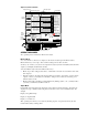
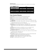
Figure 22, Zone Terminal
MONITOR
ADJUST
TIME SCHEDULE
PASSWORD
ENTER
Compressor 1
Compressor 2
Stage 3
Stage 4
Solenoid #1
Frzstat#1Alm
Frzstat#2Alm
MinLowPres#1
MinLowPres#2
Occupied
Flow Failure
OA Lockout
Cir#2Lead=On
Pmp/Stp #1=0
Lvg Water Temp
Evap Pres #1
Evap Pres #2
OA/AI3 Input
LvgWtr RBnd SP
Contrl Band SP
Actual Lvg SP
Unoccpd Lvg SP
OA Lockout SP
Lvg Low Lim SP
SoftSta Capcty
Cir #1 Starts
Cir #2 Starts
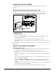
McQuay AGZ/AGR Global Chiller
INSERT 10
ON OFF
Display
Button 1
Mode
Selector
Panel
Mode
Selector
Button
2
AGZ-AGR
Display Indicator Dot
On/Off Status
3
Oper ating Mod e Indic ator
Up/Do wn Arrow Keys
Door
Display Item List
Warning Signal
ALARM
OA/AI3 HiLimSP
OA/AI3 ResetSP
Display Area 11
Display Area 21
Display Area 31
Alarm Light
Lvg Water SP
% Unit Load
SoftStart Time
Pmp/Stp #2=0
Solenoid #2
Stage 5 Opt.
Stage 6 Opt.
OPERATING MODES
Two operating modes are included: Monitor and Adjust.
Monitor Mode
As soon as the ZT is connected, it completes a self-check, and starts up in the Monitor Mode.
Monitor Mode lets you view up to three of chiller settings/sensed values at a time.
To allow you to monitor your system, a clear plastic insert (factory made and installed) relates the ZT’s
output to your McQuay Global UNT controller.
You can simultaneously monitor the chiller in three ways:
• Monitor up to three settings/sensed values. A maximum of six items are accessible in each of the
three displays.
• Read the symbols to the right of the display numbers to learn the on/off status of various inputs,
outputs, or modes (| = On status; m = Off status). This provides continuous monitoring of 18
different status (on/off).
• Monitor alarm status–a flashing red alarm light and any flashing symbol ( |, m, s) visually notifies
you when your chiller has an alarm condition.
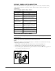
Adjust Mode
In Adjust Mode, the ZT displays information in each of the three numerical displays. Typically, the
displays are set up so that the relationship between the values can be viewed simultaneously. For
example:
Display 1 = Lvg Water Temp
Display 2 = Lvg Water SP
Display 3 = % Unit Load
This operating mode allows you to adjust any flashing setpoints. Setpoints adjusted by the ZT
remain in effect until you change them.