SERVICE GUIDE BOOK
McQuay Service Guide Book Table of Contents 1.0 2.0 3.0 4.0 5.0 6.0 7.0 Model Name 1.1 Product Name Description 1.2 Nomenclature ............................... ............................... 2 3 Conversion Table 2.1 Conversion Table ............................... 5 Product Mainboard vs. Handset Matrix 3.1 Product Mainboard vs. Handset Matrix ............................... 6 Controller Development History 4.1 Controller Development History ...............................
McQuay Service Guide Book 1.0 Model Name 1.1 Product Name Description No.
McQuay Service Guide Book 1.
McQuay Service Guide Book Outdoor Unit Others A : First Issue Specifications Variation O : Standard Unit I : Gold Fins G : Low Ambient Unit H : High Ambient Unit Compressor P : Panasonic M : Mitsubishi Market Region C : Export with CE mark Electrical A : 220-240V/1Ph/50Hz F : 380-415V/3Ph/50Hz M LC 010 C R - A C P O Model Type R : Heat Pump Omitted if Cooling Only Series C : C Series Capacity 010 : 10,000 Btu/h Inverter Series X : X - series Y : Y – series Omitted if non-inverter Model Name LC
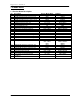
McQuay Service Guide Book 2.0 Conversion Table 2.1 Conversion Table Capacity Btu/hr 1 1000 3.968 3412 MBH 0.001 1 0.004 3.412 kCal/Hr 0.252 252 1 860.04 kW 0.293 x 10⁻³ 0.293 -3 1.162 x 10 1 Pressure kg/cm 1 14.22 3.61 x 10⁻² 1.45 x 10⁻⁴ 0.07 1 2.538 x 10⁻³ 0.1 x 10⁻⁴ Flow Rate W.G. 2 PSI (in.) 27.7 394.08 1 0.004 3 L/s 1 0.278 1000 0.063 0.472 3 m /hr 3.6 1 3600 0.227 1.7 m /s 0.001 0.278 x 10⁻³ 1 -3 0.063 x 10 -3 0.472 x 10 Temperature fps 1 3.281 0.017 ° F − 32 1.8 Volume L 1 1000 3.
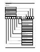
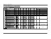
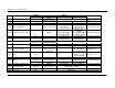
McQuay Service Guide Book 3.0 Product Mainboard vs. Handset Matrix Main Board (IC) Type No. 1 2 3 4 5 6 7 8 9 10 DX 11 12 13 14 15 L2.0 L2GSN L208A W_2_03A U1SB125 SQ2.0 VA2.0 2P206569-4 VA3.
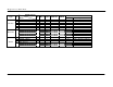
McQuay Service Guide Book Main Board (IC) Type CW FCU No. 13 14 15 16 17 18 19 Mini Chiller WSHP 20 21 22 23 W2 Model WM – GW Series CK – AW/AWH/CW Series CE – DW Series CE – EW Series CC – CW Series SB – BW Series AC – C Series AC 20 – 60C/CR AC 80 – 150C/CR 5AC 20 – 25C/CR 5AC 30 – 55C/CR 5WMWS – GR 5CKWS – AR/CR 5CCWS – CR WH – B Series WH 11 – 20B/BR WH 25 – 70B/BR MC1.
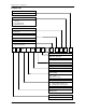
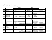
McQuay Service Guide Book 4.0 Controller Development History Year Main Board 1996 Handset Model Wireless Wired Challenger 2.1 & 2.2 G3 - 1996 Challenger 2.2 G3 - 1997 Challenger 2.4 G3 & G6 - 1998 Challenger 2.
McQuay Service Guide Book Handset Wireless Year Main Board 2002 Chilled Water W1V3 G6 2002 2003 Multi Split Indoor, MS10.0 Mini Chiller MCH03A G7 - Wired SLM3 / Netware 2 (optional) SC302 2003 Universal U1SB125 - SLM3 – single speed 2003 Sequential Controller, SQ - SQ-LCD 2004 U1.4 G8 - 2004 L2.
McQuay Service Guide Book 5.0 Handset Operating Guide 5.1 G6 Outlook Operation Guide 1. “ON/OFF” Switch • Press to start the air conditioner unit. • Press again to stop the unit. 2. Temperature Setting • Set the desire room temperature. • Press button to increase or decrease the set temperature. Setting range are between 16°C to 30°C setting (60°F to 80°F) (Optional setting from 20°C to 30°C). • Press ▲ or ▼ button simultaneously will toggle the temperature setting between °C and °F. 3.
McQuay Service Guide Book 5. Timer Setting Press set button to activate the timer setting (from 1 hour to 15 hour) of the air conditioning unit. It will be in “On” or “Off” condition after the set time depending to the current condition (either from “On” to Off” or vise versa) To cancel the timer setting, press the button continuously until the timer display goes off. 6. Operation Modes • Press the “mode” button for select the type of operating mode. • Cooling only unit: Cool → Dry → Fan.
McQuay Service Guide Book 5.2 G7 Outlook Operation Guide 1. Transmission Source • The source where the signal will be transmitted. 2. Signal Transmission Indication • Blink to confirm the last setting has been send to the unit. 3. On/Off Button • Press once to start the air conditioner. • Press again to stop the unit. 4. Temperature Setting • To set the desired room temperature, press the button to increase or decrease the set temperature.
McQuay Service Guide Book 5. Operation Mode • Press the MODE button to select the type of operating mode. • For cooling only unit, the available modes are: COOL, DRY & FAN. • For heat pump unit, the available modes are: AUTO, COOL, DRY, FAN & HEAT. 6. Fan Speed Selection • Press the button until the desired fan speed is achieved. 7. On Timer Setting • Press the SET button will activate the on timer function. • Set the desired on time by pressing the SET button continuously. If the timer is set to 7.
McQuay Service Guide Book 5.3 G11 Outlook Operation Guide 1. “ON/OFF” Button • Press once to start the air conditioner unit. • Press again to stop the unit. 2. Temperature Setting • To set the desired room temperature, press ▲ the button to increase or ▼ button to decrease then set temperature. • The temperature setting range is from 16°C to 30°C. • Press both buttons simultaneously to toggle and from ▲ °C to▼ °F setting. 3. Operation Mode • Press the MODE button to select the type of operating mode.
McQuay Service Guide Book 4. Fan speed selection • Press the button continuously will toggle the fan speed in the following order: Low ( Med ( ) –––: High ( ) –––: Auto • Stop pressing when the desired fan speed appears on the display screen. ) –––: 5. ON Timer Setting • Press the SET button will activate the on timer function. • Set the desired on time by pressing the SET button continuously. If the timer is set to 7.30am, the air conditioner will turn on at 7.30am sharp.
McQuay Service Guide Book 5.3 G17 Outlook Operation Guide 1. Transmission Source • The source where the signal will be transmitted. 2. Signal Transmission Indication • Blink to confirm that the last setting has been transmitted to the unit. 3. Temperature Setting • To set the desired room temperature, press the ▲ or ▼ button to increase or decrease the set temperature. • Temperature setting range is from 16°C to 30°C (optional setting 20°C to 30°C). 4.
McQuay Service Guide Book 5. Automatic Air Swing (optional) • Press the SWING button to activate the automatic air swing function. • To distribute the air to a specific direction, press the SWING button and wait until the louver move to the desired direction and press the button once again. 6a. Silent Function (For WM – J Series only) • Press for quiet operation. • Fan speed turn to minimum speed. • Press again to deactivate the function. 6b.
McQuay Service Guide Book 5.4 GS01 1 2 3 6 4 5 7 13 9 12 8 11 10 Operation Guide 1. Transmission Source • The source where the signal will be transmitted. 2. Signal transmission indication • Blink to confirm that the last setting has been transmitted to the unit. 3. ON/OFF Button • Press once to start the air conditioner unit. • Press again to stop the unit. 4.
McQuay Service Guide Book 5. Operation mode • Press the MODE button to select the type of operating mode. • For cooling only unit, the available modes are: COOL , DRY and FAN . • For heat pump unit, the available modes are: AUTO , COOL , DRY , FAN and HEAT . • The AUTO mode is unavailable for chilled water system. • 6. Automatic air swing • Press the SWING button to activate the automatic air swing function.
McQuay Service Guide Book 12. Sleep mode setting • Press the button will activate the sleep mode function. • This is an energy saving option. When the unit is operating under cooling mode, the set temperature is increased by 0.5°C after the first half an hour, another 0.5°C after the second half an hour and 1°C after the following 1 hour.
McQuay Service Guide Book 5.5 APJ1 Outlook 1 2 5 6 7 8 3 9 4 10 12 13 2 11 Operation Guide 1. Transmission Source • The source where the signal will be transmitted. 2. LCD Display • It displays the current settings. • (In this illustration, each section is shown with its displays on for the purpose of explanations) 3. ECONO button • ECON operation is a function which enables efficient operation by limiting the maximum power consumption value.
McQuay Service Guide Book 4. POWERFUL Button • • • POWERFUL operation quickly maximizes the cooling (heating) effect in any operation mode. To start POWERFUL operation, press . POWERFUL operation ends in 20 minutes. Then the system automatically operates again with the previous settings which were used before POWERFUL operation. is displayed on the LCD. To cancel POWERFUL operation, press button again. disappears from the LCD. 5. Temperature Settings. • It changes the temperature settings. 6.
McQuay Service Guide Book 11. ON TIMER Operation • To use ON TIMER operation, press button. • is displayed on the LCD. Each pressing of The timer can be set between 1 to 12 hours. • To cancel ON TIMER operation, press button. advances the time setting by 1 hour. will disappear from the LCD. 12. OFF TIMER Operation • To use OFF TIMER operation, press button. • is displayed on the LCD. Each pressing of timer can be set between 1 to 9 hours. • To cancel OFF TIMER operation, press button. 13.
McQuay Service Guide Book 5.6 SLM3 Outlook Operation Guide 1. “ON/OFF” Switch • Press to start the air conditioner unit. • Press again to stop the unit. 2. Temperature Setting • Set the desired room temperature. • Press button to increase or decrease the set temperature. • Setting range are between 16°C to 30°C (60°F to 80°F). 3. Operation Modes • Press the “mode” button for select the type of operating mode.
McQuay Service Guide Book 6. “SLEEP” Mode • Press button to activate the sleep function. This function can only be activated under “cool” or heating mode operation. When it is activated under “cool” mode operation, the set temperature will increase 0.5°C after 30 minutes, 1°C after 1 hour and 2°C after 2 hours. If it is activated under “HEAT” mode operation, the set temperature will be decreased 0.5°C after 30 minutes, 1°C after 1 hour and 2°C after 2 hours. 7.
McQuay Service Guide Book 5.7 Sequential Controller Outlook A : Time display B : Error indication C : Compressor running display (up to 4 compressors) D : Key lock display E : Heat display (up to 2 heaters) F : Energy saving mode display G : Compressor deforst cycle display (up to 4 compressors) H : Operation mode display I : Temperature set display Operating Guide 1. “ON/OFF” Switch • Press once to start the air conditioning unit. • Press again to stop the unit.
McQuay Service Guide Book 5. Temperature Setting • To set the desired room temperature, press or to increase or decrease the set temperature in the range of 16°C to 30°C. • Press both and simultaneously to toggle between °C and °F setting. 6. Time Setting Real time clock • Press the CLOCK key once to activate set clock mode. • Press again to disable set clock mode. • Under set clock mode, the time of the present day can be set by pressing the respective MINUTE, HOUR and DAY key.
McQuay Service Guide Book 5.8 Netware 3 Outlook 4 5 6 3 2 7 1 8 1. 2. 3. 4. 5. 6. 7. 8. Time display Key lock display Error indication Fan speed display Operation mode display Sleep mode display Air swing display Temperature set display Operating Guide 1. “ON/OFF” Switch • Press once to start the air conditioning unit. • Press again to stop the unit. • The operation lamp next to the key lights up and goes off respectively when the unit is running or not running.
McQuay Service Guide Book 2. Selecting Operating Mode • Press the MODE key to select the type of operating mode. Consecutive press of the key switches the operation over “COOL”, “HEAT”, “AUTO”, “DRY” and “FAN” 3. Fan Speed Selection • Press the FAN key until the desired fan speed is achieved. 4. Sleep Mode Setting • Press the SLEEP key to activate sleep mode. This function is available under COOL, HEAT & AUTO mode. • When it is activated in COOL mode, the set temperature will be increased 0.
McQuay Service Guide Book 6.0 Controller Configuration 6.1 Auto Random Restart • • Shorted at JH/JP1/J_LST jumper at main board for auto restart (supplied). Remove the jumper to have non-auto restart. D2.0 U1.5 / SQ2.0 L2.
McQuay Service Guide Book 6.2 Hot Keep Selection Three selections available: a. Fan stop if indoor coil temperature < 30°C (OFF). b. Fan runs at low speed if indoor coil temperature < 30°C and stop if indoor coil temperature < 18°C (ON). c. Cycle of low fan running for 30s and fan off for 120s and repeat (INTERVAL). WM – F/FR (U1.5 & L2EF) 3 selections available at the slide switch on the On/Off Switch Board; Preset at OFF. Other models (U1.5) At CN3 location on the PCB, i.
McQuay Service Guide Book L2 Models Two selections are available: a. Fan ON: - If the indoor coil temperature > 40°C, the indoor fan will run at speed. - If the indoor coil temperature crosses 37°C, the indoor fan willrun at low speed. - if the indoor coil temperature <18°C, the indoor fan will stop. b. Fan OFF - If the indoor coil temperature >40°C, the indoor fan will run at set speed. - If the indoor coil temperature crosses 37°C, the indoor fan willrun at low speed.
McQuay Service Guide Book 6.3 Auxiliary Heater Conversion U1.5 Heatpump with Auxiliary Heater To convert the standard U1.5 heatpump PCB to with auxiliary heater application, the following components need to be added onto the PCB. 1. Heater relay 2. Transistor 3.
McQuay Service Guide Book To convert SB125 heatpump PCB to auxiliary heater application, you need only one heater relay as shown below: 1. Place the JM relay on the RY_HTR location 2. Solder all the relay pins.
McQuay Service Guide Book W2 Heatpump with Auxiliary heater To convert SB125 heatpump PCB to auxiliary heater application, you need the following components to be added onto the PCB: 1. Shunt jumper 2. JM Relay 240VAC/ 20A Step 1:Place the shunt jumper at jumper header M2. Step 2:1. Place the JM relay at RY_HTR location 2.
McQuay Service Guide Book 6.4 Multi Split Conversion Cooling Only Model (L2.0 / L208A) The cooling only model WM-G, CK-A/B/C/E, CE-E, CC-C which are using L2 control board can be switched to multi split units without any modification needed. Heatpump Model (L2.0) WM-GR The Multi Split mode can be selected at the slide switch on the On/Off Switch Board; Preset at OFF. The outdoor coil sensor has to be removed from the PCB as the reading is taken from the outdoor PCB directly.
McQuay Service Guide Book 6.5 Sequential Controller It is allowed to configure the controller to suit individual’s need with details below: 1. Models For each type, there are 3 models for the control to configure into. a. Cooling (SQCn) b. Heatpump + no heater (SQHn0) c. Heatpump + 1 heater (SQHn1) d. Heatpump + 2 heater (SQHn2) e. Auto heatpump + no heater (SQHn0) f. Auto heatpump + 1 heater (SQHn1) g.
McQuay Service Guide Book 5. Last Memory Functions The power up settings for either with or without the last memory backup is based on the J_LST setting. J_LST Setting J_LST Plugged J_LST Removed a. Last memory backup b. Without last memory backup 6.
McQuay Service Guide Book 7.
McQuay Service Guide Book 9. Conversion from Old Sequential Board to New Sequential Board (For wiring up to 1000 meters) 9.1 Sequential Main Board SQMB01 (Old Version) Rework instruction: SQMB01 (Main Board) from old version to new version Step 1: Remove Jumper J1 and J2. Step 2: Add Part: 2051-MAX1483 IC :MAX1483 to U8 U8 J1 & J2 9.
McQuay Service Guide Book 9.3 Sequential Main Board SQMB01 (New Version) Part: 2051-MAX1483 IC :MAX1483 Jumper J1 and J2 removed 9.4 Sequential LCD Panel SQ-LCD (New Version) SQLCD (LCD Panel) from old to new Step 1: Remove Jumper: J1, J2 Step 2: Add Chip Resistor.
McQuay Service Guide Book 6.6 Chilled Water Fan Coil Unit (W1V3) The standard W1V3 board comes with a VALVE jumper. The system can be configured as the jumper selection listed below: VALVE jumper √ X √ X Heatpump Mode & Valve Application Heatpump Mode & Valveless Application Cooling Mode & Valve Application Cooling Mode & Valveless Application √ : Jumper Remained HEAT jumper √ √ X X X : Jumper Removed VALVE & HEAT Jumper Location Model: WM 05-25FW 1.
McQuay Service Guide Book 6.7 Chilled Water Fan Coil Unit (W2.0) The system model can be configured via the following jumpers. For each model selected, the permissible operating modes are as follows: Jumper M1 M2 M3 M4 Configuration 2 Pipes without Aux. Heater 2 Pipes with Aux. Heater 4 Pipes + Boiler 4 Pipes + Boiler Model 1 2 3 4 Operating Modes Heat>Cool>Dry>Fan Heat>Cool>Dry>Fan Heat>Cool>Dry>Auto>Fan Heat>Cool>Dry>Fan M1 M2 M3 M4 The standard W2 board comes with a VALVE jumper.
McQuay Service Guide Book 6.8 U1.5 L208A Conversion All single split indoor units with U1.5 PCB cannot be directly by the new L208A PCB because of the following:MCK/A5CK-A/AR & MCK/A5CK-C/CR U1.5PCB - The connector on the PCB (CN6) for the inter-connector cable has 16 pins. L208A PCB - The connector on the PCB (CN5 & CN6) for the inter-connector cable have 12 & 2 pins. MCM/A5CM-D/DR & MCM/A5CM 062C/CR U1.5 PCB - The connector on the PCB (CN6) for the assy.
McQuay Service Guide Book 6.9 WMF U1.4 to L2EF Conversion 1. The U1.4 PCB can be replaced directly by the new L2EF PCB because no modification needs to be done and the connector pins for both stepper motor and fan motor is still the same as U1.4. 3. However, the display panel (IR receiver) and On/Off switch board pins on PCB for both U1.4 and L2EF is not compatible with each other; therefore it is unable to change only the display panel or On/Off switch board from U1.4 to L2EF or L2EF to U1.4. 5.
McQuay Service Guide Book 7.0 Service Diagnosis 7.1 Self Diagnosis Table Wall Mounted F Series Cooling Only Model Model WM 010/015/020/025F, 311 Board D2.
McQuay Service Guide Book Wall Mounted F Series Heat Pump Model Model WM 010/015/020/025FR, 301R Board U1.
McQuay Service Guide Book Wall Mounted F Series Cooling Only Model Model WM 007/010/015/020/025F Board L2EF Handset G7 LED Indicator Light Display TIMER Mode POWER ON SLEEP Mode DRY MODE LED Indication Lights: Normal Operation and Faulty Indication Table Operation / Faulty Indication Timer On Sleep mode On Dry mode / Continuously Room air sensor contact loose / short Once every 2 sec Indoor coil sensor contact loose / short Twice every 2 sec Outdoor abnormal operation 3 times every 2 sec ON
McQuay Service Guide Book Wall Mounted F Series Heatpump Model Model WM 007/010/015/020/025FR, 311/301R Board L2EF Handset G7 LED Indicator Light Display / COOL Mode (Green) DRY Mode (Orange) HEAT / FAN Mode (Red / Green) SLEEP Mode (Red) The heat pump unit is equipped with “auto mode”, whereby the unit will provide reasonable room temperature by switching the unit automatically to either “cool” mode or “heat” mode, according to the temperature setting set by the user, LED Indicator Lights: Normal
McQuay Service Guide Book Wall Mounted G Series Model Model WM 010/015/20/025G/GR Board L2.
McQuay Service Guide Book Wall Mounted J Series Model Board L2GSN Model WM 009/015J/JR Handset G17 Led Indicators Light Display Sleep Cool/ Heat Timer LED Indoor lights: Normal Operation and Fault Conditions for Cooling/ Heat Pump Unit Error Code Operation / Faulty Indication (GREEN/RED) / Green / Red / Red / Green 1 time 3 times 2 times 1 time - Cooling mode - Heating mode - Auto mode in heating operation - Auto mode in cooling operation - Timer On - Sleep mode On - Fan mod
McQuay Service Guide Book Ceiling Cassette A / B / C Series Model Model CK 020/025/030/040/050A/AR CK 015/020/025B/BR CK 010/015/020C/CR Board U1.5 U1.5 U1.
McQuay Service Guide Book Ceiling Cassette A / B / C/ E Series Model Model CK 020/025/030/040/050A/AR CK 015/020/025B/BR CK 010/015/020C/CR CK 020/025/028/040/050E/ER Board L208A L208A L208A L208A Handset G17 / SLM3 / Netware 3 G17 / SLM3 / Netware 3 G17 / SLM3 / Netware 3 G17 LED Indicator Light Display - Cooling POWER TIMER SLEEP LED Indicator Light Display – Heating POWER TIMER HEAT LED Light Diagnostic Table Operation / Faulty Indication Cooling mode Timer On Sleep mode On Heating mode Auto
McQuay Service Guide Book Ceiling Exposed D Series Model Model CE 020/025/030/040/050D/DR Board U1.
McQuay Service Guide Book Ceiling Exposed D / E Series Model Model CE 020/025/0300/400/50D/DR CE 015/020/0250/28E/ER Board L208A L208A Handset G18 / SLM3 / Netware 3 G18 / SLM3 / Netware 3 LED Indicator Light Display - Cooling COOL DRY FAN LED Indicator Light Display – Heating COOL DRY FAN HEAT LED Light Diagnostic Table Operation / Faulty Indication Cooling mode Dry mode Fan mode Heating mode Auto mode in cooling operation Auto mode in heating operation Compressor overload protection / Indoor
McQuay Service Guide Book Seven Segment Display – SLM3 / Netware 3 Model WM 010/015/020/025FR, 301R CK 020 - 050A/AR CK 015 - 025B/BR CK 010 - 020C/CR CE 020 - 050D/DR CC 010 - 060C/CR Board U1.5 U1.5 U1.5 U1.5 U1.5 U1.
McQuay Service Guide Book Ducted Blower B/C/D/ER Series Model – Single Compressor Rooftop Packaged Air Conditioner – Single Compressor Model SB 075 – 100B/BR SB 075 – 100D SB 075 – 100ER SB 125 – 150B/BR SB 125CR SB 125 – 150D SB 125 – 150ER Board L208A L208A L208A U1SB125 U1SB125 U1SB125 U1SB125 Handset SLM3 SLM3 SLM3 SLM3 SLM3 SLM3 SLM3 RT 055 – 120A/AR U1SB125 SLM3 Seven Segment Display – SLM3 Seven Segments Faulty Indication E1 blinking Room air sensor contact loose / short E2 blinking Indoo
McQuay Service Guide Book Ducted Blower B/D/ER Series Model – Multi Compressors Rooftop Packaged Air Conditioner – Multi Compressors Model SB 150B2/BR2 – 600B4/BR4 SB 125D2 – 500D4 SB 125ER2 – 600ER4 Board SQ2.0 SQ2.0 SQ2.0 Handset SQ-LCD SQ-LCD SQ-LCD RT 150 – 420A/AR SQ2.0 SQ-LCD Error Code When the system is on and an error occurs, the ON/OFF LED on the LCD panel will blink and an error code is shown.
McQuay Service Guide Book Wall Mounted F Series Inverter-X Model Model WMX 010/015FR Board VA2.
McQuay Service Guide Book Wall Mounted G Series Inverter-X Model Model WMX 010/015/020/025G/GR Board VA2.
McQuay Service Guide Book Ceiling Cassette A/C Series Inverter-X Model Model CKX 020/025A/AR CKX 010/015/020C/CR Board VA3.0 VA3.
McQuay Service Guide Book Ceiling Convertible E Series Inverter-X Model Model CEX 015/020/025E/ER Board VA3.
McQuay Service Guide Book Seven Segment Display Board VA3.0 VA3.0 VA3.0 VA3.0 VA3.
McQuay Service Guide Book Inverter - X Outdoor Unit Model SLX 010/105/020/025C/CR MSV 025/035A MSX 020/025/030A/AR Board VB2.0 VB2.0 VB2.0 Normal running / compressor running RED LED blinking No.
McQuay Service Guide Book Chilled Water Fan Coil Unit Model WM 005 – 025FW, 301W CK 020 – 050AW/AWH CK 015 – 025BW CK 010 – 020CW CE 020 – 050DW/CBW CC 010 – 060CW SB 075 – 150BW Board W1V3 W1V3 W1V3 W1V3 W1V3 W1V3 N/A Handset G7 / SLM3 / Netware 3 G7 / SLM3 / Netware 3 G7 / SLM3 / Netware 3 G7 / SLM3 / Netware 3 G7 / SLM3 / Netware 3 SLM3 / Netware 3 No Controller Self Diagnostic Table – W1V3 Fault Indication POWER LED / COOL LED Room sensor missing Blinks 4 times Indoor coil sensor missing Blinks 4 ti
McQuay Service Guide Book Wall Mounted G Series Model – Water Source Split Unit Model 5WMWS 010/015/020/025GR Board LWS2.
McQuay Service Guide Book Ceiling Cassette A / B / C Series Model – Water Source Split Unit Model 5CKWS 020/025/030/040/050AR 5CKWS 010/015/020CR Board LWS2.0 LWS2.
McQuay Service Guide Book Seven Segment Display – SLM3 / Netware 3 (Water Source Split Unit) Model 5WMWS 010/015/020/025GR 5CKWS 020 - 050A/AR 5CKWS 010 - 020C/CR 5CCWS 010 - 060C/CR Board LWS2.0 LWS2.0 LWS2.0 LWS2.
McQuay Service Guide Book Inverter-Y Model Indoor Series Model 5WMY 010/015/020/025 JR 5CKY 010/015/020CR 5CKY 020/025/028/040/050 ER 5CEY 062 CR 5CEY 020/025/028/040/050 ER 5CCY 020/025/028/038/050/060 CR Board Handset G17 G17 G17/ GS01 GS01 G17/ GS01 G17/ GS01 LED Indicator Lights: Normal Operation and Fault Conditions for Heat Pump Unit Operation / Faulty Indication COOL/HEAT (GREEN/RED) Cooling mode Green Heating mode Red Auto mode in heating operation Red Auto mode in cooling operation Gre
McQuay Service Guide Book Inverter-Y Model Indoor Series Error Code Diagnosis by Wireless Handset G17 Temperature Display Section ON/OFF Button Mode Button ON TIMER CANCEL Button OFF TIMER CANCEL button Diagnosis Step 1. Hold down TIMER CANCEL button for 5 seconds, a “ ” indication flashes on the temperature display section. 2. Press TIMER CANCEL repeatedly until indoor buzzer produces a long beep.
McQuay Service Guide Book Error Codes Error Codes 0 Error Description Error Codes Error Description Normal F6 U0 Insufficient gas H0 U2 U4 DC voltage out of range Communication error Signal transmission error (on outdoor unit PCB) Installation error H3 H6 Heat exchanger overheat Compressor sensor system abnormality High pressure switch error Position sensor abnormality H8 AC current sensor error U7 UA H9 Outdoor air thermistor short / open UF Communication Error (indoor and outdoor) pipi
McQuay Service Guide Book Single Split Inverter – Y Model Outdoor Unit Model 5LCY 010/015/020/025 DR 5LCY 030/040/0500/60 DR Board W_2_03A W_2_03A Handset G17 G17 Error code diagnosis by Outdoor 7-segment Display In the Y-series model, the 7-segment display section on the outdoor unit indicates the following: 1. Unit running parameters 2. Error codes Unit Condition Unit in normal operating mode Unit is in fault Display on 7-segment 1.
McQuay Service Guide Book Parameter Number 31 32 33 34 35 36 37 38 39 40 41 42 43 44 45 46 47 48 49 50 51 52 53 Parameter Description De-ice setting Dew drop setting Heat sink protection zone Turbo setting Silent setting Low ambient zone Defrost status Pump down status O/D output flag O/D output capacity Target discharge temp EXV control status Indoor fan tap O/D error code I/D error code Low voltage control zone Gas leak detection Discharge sensor disconnected Official test setting Skip frequency flag La
McQuay Service Guide Book Multi Split Inverter – Y Outdoor Unit Model 5MSY 025/030 BR Board Handset G17 Error code diagnosis by Outdoor 7-segment Display The outdoor unit LED indicates the running condition of the system: LED INDICATION Green Red A 1 2 3 Description 4 ◑ ● ● ● ● ◑ ◑ ◑ ◑ ◑ ◑ ◑ ◑ ◑ ◑ ◑ ◑ ● ● ● ● ● ● ○ ○ ○ ○ ○ ○ ● ● ● ○ ○ ○ ● ● ● ● ● ○ ● ○ ○ ● ○ ○ ● ● ○ ○ ○ ● ○ ● ○ ○ ● ○ ● ○ ● ● ○ ● NORMAL INSTALLATION ERROR ANTIFREEZE (OTHER ROOMS) HEAT SINK OVERHEAT IPM ERROR / IGBT ERROR INSUFFICI
McQuay Service Guide Book Wall Mounted K-Series Inverter-Y model Model 5WMY 010/015 KR Board 2P206569-4 Handset APJ1 Indoor LED Indication The operation lamp flashes when any of the following errors is detected. 1. When a protection device of the indoor or outdoor unit is activated or when the thermistor malfunctions, disabling equipment operation. 2. When a signal transmission error occurs between the indoor and outdoor units.
McQuay Service Guide Book CATEGORY OUTDOOR UNIT CODE EA E1 E5 E6 E7 E8 F3 F6 H0 H6 H8 H9 J3 J6 L3 L4 L5 P4 DESCRIPTION COOLING-HEATING SWITCHING ERROR CIRCUIT BOARD FAULT OL STARTED FAULTY COMPRESSOR START UP DC FAN MOTOR FAULT OVERCURRENT INPUT HIGH TEMPERATURE DISCHARGE PPE CONTROL HIGH PRESSRUE CONTROL (IN COOLING) SENSOR FAULT OPERATION FAULT DUE TO FAULTY POSITION DETECTION SENSOR DC CURRENT SENSOR FAULT FAULTY SUCTION AIR TEMPERATURE SENSOR FAULTY DISCHARGE PIPE TEMPERATURE SENSOR FAULTY HEAT EXCH
McQuay Service Guide Book Multi Digital Scroll Indoor Units Model WMD 009/010/015/020/025 G CKD 020/025/030/040/050 A CKD 010/015/020 C CCD 010/015/020/025/030/040/050/060 C CMD 020/025/028 E CMD 040/050 D CMD 062 C DBD 080/0100 5WMD 009/100/015/020/025 G 5CKD 020/025/030/035/040/050 A 5CKD 010/015/020 C 5CCD 010/015/020/025/030/040/050/060 C 5CMD 020/025/028 E 5CMD 040/050 D 5CMD 062 C DBD 080/100 Board MC201-C MC201-C MC201-C MC201-C MC201-C MC201-C MC201-C MC201-A MC201-C MC201-C MC201-C MC201-C MC201-
McQuay Service Guide Book Error Diagnosis by Wired Controller (MC301) ITEM 1 2 3 4 5 6 7 8 9 10 11 12 13 14 15 16 17 18 19 20 21 22 23 24 25 26 27 28 29 30 31 32 33 34 35 36 37 38 39 40 41 42 43 44 45 46 47 48 49 50 51 52 53 54 55 56 57 58 59 60 61 62 63 64 65 66 CODE E0 E1 E2 E3 E4 E5 E6 E7 E8 E9 EA EB EC EF F0 F1 F2 F3 F4 F5 F6 F7 F8 F9 FA FB FC FE H0 H1 H2 H3 H4 H5 H6 L0 L1 L2 10 11 12 13 14 15 16 17 18 19 1A 1B 1C 1F 20 27 28 29 30 31 32 33 34 35 36 40 41 42 DESCRIPTION System malfunction Sensor Brok
McQuay Service Guide Book Multi Digital Scroll Outdoor Units Model MDS 030/040/050/060/070 A/AR MDS 080/100/120/150/180/200/240/ 260/300/320 B/BR 5MDS 080/100/120/140/160/180/ 200/220/240/260/280/300/320/340/360 /380/400/420/440/460/480/500 B/BR Board - Handset G17/ MC301 G17/ MC301 - G17/ MC301 Outdoor Error Code Error code diagnosis by PCB four Digit 7-Segment MDS Outdoor A Series Error Code ITEM 1 2 3 4 5 6 7 8 9 10 11 12 13 14 15 CODE E0 E1 E2 E3 E4 E5 E6 E7 E8 H1 H2 H3 L1 CCX DESCRIPTION Discha
McQuay Service Guide Book 7.2 General Check When any air conditioner malfunction is noted, immediately switch off the power supply to the unit and contact the local dealer if necessary.
McQuay Service Guide Book 7.3 General Troubleshooting Guide By means of pressure readings. Too High A Little High Probable Cause Normal Circuit A Little Low Data Too Low Pressure 1. Overcharged with refrigerant. 2. Non-condensable gases in refrigerant circuit (eg. Oil) 3. Obstructed air-intake / discharge. 4. Short circuit of hot air at condensing unit. 1. Poor compression / no compression (compressor defective). 2. Check valve stick in open position. 3.
McQuay Service Guide Book By means of diagnostic flows chart: Generally, there are two kinds of problems, i.e. starting failure and insufficient cooling/ heating. “Starting failure” is caused by electrical defect while improper application or defects in refrigerant circuit causes “insufficient cooling/ heating”.
McQuay Service Guide Book 1 2 Condenser fan contactor Compressor contactor Coil burnt Change the contactor Contact faulty Change the contacts Fan motor faulty Repair or change the motor contactor Other electrical component faulty Repair or change if necessary Coil burnt Change the contactor Contact faulty Change the contacts Open compressor windings Change the compressor Fan motor faulty Correct the wiring The most common causes of air conditioner failure to ‘start’ are: a) Voltage not
McQuay Service Guide Book ii) Diagnosis of Refrigerant Circuit/ Application There might be some causes where the unit starts to run but does not perform satisfactorily, i.e. insufficient cooling. Judgement could be made by measuring temperature difference of indoor unit’s intake and discharge air as well as running current.
McQuay Service Guide Book Insufficient Heating Air Calculation Restricted Indoor/ outdoor dirty (clogged) Clean the coil Indoor air filter dirty Clean the filter Fan motor malfunction Change or repair the motor Obstruction at air inlet/ outlet of indoor/ outdoor unit Excessive heat source e.g. electric kettle.
McQuay Service Guide Book Mini Chiller: Troubleshooting Guide When any malfunction is occurred, immediately switch off the power supply to the unit, and contact the local dealer, if necessary. Some simple troubleshooting tips are given below: Symptoms Possible Causes Remedial Action 1.
McQuay Service Guide Book Rooftop: Troubleshooting Guide Before you ask for repair service, check the following points Symptoms Switch Box Possible Causes (Field Supply) It does not run Switch (ON) • Power failure • • • • Air flow out but it does not cool enough Switch (ON) • • • • Cool air does not come out Switch (ON) Fan runs but compressor does not run • • • The power supply is turned OFF The fuse in the power supply is gone The earth leakage breaker is gone The wiring phase of power supply is m
McQuay Service Guide Book Appendix Resistance – Temperature Characteristics Type Material Name Resistance B Value DTN-C1 03F3H-OYL 1128, 1148, 1158 3H R25=10.000kΩ + 1.0% - 1.0% B25/30=3450K + 1.0% - 1.0% t°C Rmin (kΩ) Rnom (kΩ) Rmax (kΩ) t°C Rmin (kΩ) Rnom (kΩ) Rmax (kΩ) -10 4.42E+01 4.53E+01 4.65E+01 -8 4.02E+01 4.12E+01 4.22E+01 42 5.28E+00 5.37E+00 5.45E+00 -6 3.66E+01 3.74E+01 3.83E+01 44 4.92E+00 5.01E+00 5.09E+00 -4 -2 3.33E+01 3.41E+01 3.49E+01 46 4.59E+00 4.
©2010 McQuay International www.mcquayup.