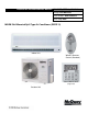
Installation and Maintenance Manual IM-5WMF (SEER13)-0706-McQuay Group: Wall Mounted Part Number: R08019028218 Date: July 2006 M5WM Wall Mounted Split Type Air Conditioner (SEER 13) Indoor Unit Wireless Remote Control (Standard) Wired Wall Control (Optional) Outdoor Unit
Table of Contents General Information……………………………………………….. 3 Safety Precautions………………………………………. 3 Unit Dimensions…………………………………………….……... 4 Indoor Units ……………………………………. ……....4 Outdoor Units …………………………….…….. ……....4 Installation Guidelines……………………………………………... 7 Installation Diagram……………………………………...7 Installation of Outdoor Unit……………………………... 7 Condensed Water Disposal of Outdoor Unit……. ……....7 Outdoor Unit Clearances……………………………7 Installation of the Indoor Unit……………………………7 Indoor Unit Clearances …………………………….
General Information This manual provides the installation procedures so your air conditioner unit operates properly and provides you the service it was designed to provide. Special adjustment may be necessary to suit local requirements. Before using your air conditioner, please read this instruction manual carefully and keep it for future reference. ! CAUTION Use copper conductors only. Unit terminals are not designed to accept other types of conductors.
Unit Dimensions Model: M5WM10F, 10FR – Indoor Unit Model: M5WM15F, 15FR, 20F, 20FR – Indoor Unit Page 4 IM-5WMF(SEER13)-0706
Model: M5WM25F, 25FR – Indoor Unit Model: M5LC10C, 10CR, 15C, 15CR – Outdoor Unit Dimension 10C/CR 15C/CR Dimension 10C/CR 15C/CR A 33-5/8” 33-5/8” B 24-3/4” 28-3/4” C 12-7/8” 12-7/8” D 7/8” 7/8” I 5/8” 5/8” J 14-1/4” 14-1/4” K 6-1/2” 6-1/2” L 3” 3” IM-5WMF(SEER13)-0706 E 2-5/8” 2-5/8” F 23-3/4” 23-3/4” G 5” 5” H 15-3/8” 15-3/8” M 2-7/8” 2-7/8” Page 5
Model: M5LC20C, 20CR, 25C, 25CR – Outdoor Unit Page 6 IM-5WMF(SEER13)-0706
Installation Guidelines Installation Diagram Condensate Disposal of Outdoor Unit (Heat Pump Unit Only) Room Cabinet Indoor Unit • There are 2 holes on the base of outdoor unit for condensed water to flow out. Insert the drain elbow to one of the holes. • To install the drain elbow, first insert one portion of the hook to the base (portion A), then pull the drain elbow in the direction shown by the arrow while inserting the other portion to the base.
Piping Mounting Plate Installation The refrigerant piping can enter the indoor unit at several different locations. Use the knock outs provided in the room cabinet. See Figure 4. The mounting plate ships attached to the back of the indoor unit. To detach for mounting on wall, remove plastic rivet from bottom (pry loose with a knife blade) and unhook. Figure 4. Indoor Unit The wall must be strong enough to support the weight of the unit. If necessary, reinforce the wall.
Installing Unit on Mounting Plate Drain Hose Installation Hook the indoor unit onto the upper portion of the mounting plate (engage the two hooks at the rear top of the indoor unit with the upper edge of the plate). Properly seat the hooks and replace the plastic rivet at the bottom. The condensate drain hose (20” long) come factory attached to the indoor unit. It is gravity flow. Avoid situations that could restrict drainage. See Figure 9. Figure 9. Drain Hose Installation Figure 8.
Figure 11. Cutting and Flaring Tube Refrigerant Tubing Tubing Length & Elevation Copper tubing to connect the indoor and outdoor units is supplied by others or it can be ordered from the factory. See Table 1 for requirements. Cover both tubes individually with 3/8” wall foam insulation. Table 1. Refrigeration Tubing Requirements Model Maximum length, ft., L Max. elevation, ft., H Max.
Electrical Connections Figure 14. Terminal Block and wire Clamp WARNING ! Improper installation can cause severe personal injury or death. Wiring must be done by a qualified electrician in compliance with local codes. Model 10F, 10FR, 15F and 15FR are using two separate power supply. Indoor unit powered by 115V/1Ph/60Hz. Outdoor unit powered by 208230V/1Ph/60Hz. • Wiring must be in accordance with all applicable electrical codes.
Figure 16. Cooling Only Size 20 & 25 Indoor Unit Terminal Block Connecting Wires Figure 17. Heat Pump Unit Size 20 & 25 Outdoor Unit Terminal Block COMP COMP L1 N2 L2 Outdoor coil sensor, 2 conductor cable, (26 feet long) shipped with the indoor unit. Extend with 22 ga. low voltage wire if not long enough to reach outdoor unit.
Wiring Diagrams INDOOR UNIT MODEL: M5WM 10F – 15F 115V OUTDOOR UNIT MODEL: M5LC 10C – 15C 208/230V IM-5WMF(SEER13)-0607 Page 13
INDOOR UNIT MODEL :M5WM 20F OUTDOOR OUTDOOR UNIT UNIT MODEL: M5LC 20C MODEL: M5LC 20C – 25C Page 14 IM-5WMF(SEER13)-0706
INDOOR UNIT MODEL: M5WM 25F OUTDOOR UNIT: MODEL: M5LC 25C IM-5WMF(SEER13)-0706 Page 15
INDOOR UNIT MODEL: M5WM 10FR – 15FR OUTDOOR UNIT MODEL: M5LC 10CR – 15CR Page 16 IM-5WMF(SEER13)-0706
INDOOR UNIT MODEL: M5WM 20FR OUTDOOR UNIT MODEL: M5LC 20CR IM-5WMF(SEER13)-0706 Page 17
INDOOR UNIT MODEL: M5WM 25FR OUTDOOR UNIT: MODEL: M5LC 25CR Page 18 IM-5WMF(SEER13)-0706
Vacuuming and Charging Purging the Piping and the Indoor Unit Charge Operation Except for the outdoor unit which is pre-charged with refrigerant, the indoor unit and the refrigerant connection pipes must be air-purged because the air containing moisture that remains in the refrigerant cycle may cause malfunction of the compressor. This operation must be done by using a gas cylinder and a precise weighing machine.
Special Precautions When Dealing With R410A Unit R410A is a new HFC refrigerant which does not damage the ozone layer. The working pressure of this new refrigerant is 1.6 times higher than conventional refrigerant (R22), thus proper installation/servicing is essential. • Never use refrigerant other than R410A in an airconditioner which designed to operate with R410A. • POE oil is used as lubricant for R410A compressor, which is different from the mineral oil used for R22 compressor.
Heat Pump Unit Table 7 shows the LED indicator lights for the heat pump unit under normal operation and fault conditions. The LED indicator lights are located at the bottom right side of the indoor unit. The heat pump units are equipped to maintain selected room temperature by switching automatically to either “cool” or “heat” mode. Figure 23. LED Indicator Lights: Normal Operation and Fault Conditions for Heat Pump Unit Table 7.
Special Features Dry Mode Overheating Protection (Heat Pump Only) • Select this mode when the standard Cool mode does not provide sufficient dehumidification. The compressor and indoor low fan will cycle together and will operate for longer periods of time to provide the increased rate of dehumidification. As a result, the room temperature differential may increase slightly. • If the indoor coil temperature exceeds 145ºF because of high ambient conditions, dirty air filter, etc.
Figure 25. Installing Filters Low Ambient Kit With this option, the unit can cool down to 32ºF outdoor temperature. (Standard units only cool down to 66ºF). To install, wire the Fan Speed Control Module (FSCM) in the outdoor unit per wiring diagram supplied with the kit. Attach the Outdoor Coil Sensor to the return bend as shown in Figure 26. Wrap sensor and return bend with insulating tape to promote accurate sensing of the refrigerant temperature. Refer also to the instructions supplied with the kit.
Remote Controller Operation Guide 1) Transmission Source • The source where the signal is transmitted. 2) Signal Transmission Indication • Blinks to confirm the last setting has been transmitted to the unit. 3) “ON/OFF” Button • Press once to start the unit. • Press again to stop the unit. 4) Temperature Setting • To set the desired room temperature, press the + or – button to increase or decrease the set temperature. • The temperature setting range is from 60ºF to 86ºF (Optional setting 68ºF to 86ºF).
11) Sleep Mode Setting • Press the SLEEP button will activate the sleep mode function. • This is an energy saving option. When the unit is operating under cooling mode, the set temperature is increased by 0.5ºC after the first half an hour, another 0.5ºC after the second half an hour and 1ºC after the following 1 hour. This function will prevent excessive cooling during summer season.
Service and Maintenance Troubleshooting ! CAUTION If any malfunction of the unit is noted, immediately switch off the power supply. Disconnect the electrical power supply before performing any service, maintenance or troubleshooting. Maintenance Schedule Item Indoor Air Filters Indoor Cabinet Outdoor Unit Maintenance Procedures Lift the return air grille and remove the filters (See Figure 23). Clean the filters by using a vacuum cleaner or wash in lukewarm water and soap.
This document contains the most current product information as of this printing. The manufacturer reserves the right to revise any of the specification and design contain herein at any time without prior notification.