
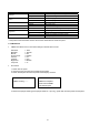
Specifications


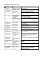
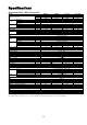


D3 Maximum duration of defrost cycle U min 10 1 40 1
D4 Defrost interval time U min 45 0 199 1
D5 Delay before defrosting U sec 0 0 1990 10
D6 Delay after defrosting U sec 120 0 1990 10
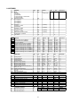
COOL MODE ANTIFREEZE Type Unit Default Min Max Resolution
A1 Antifreeze heater set-point U °C ( F) 5 (41) -40 (-40) 40 (104) 1
A2 Antifreeze heater differential U °C (°F) 2 (3.6) 0.4 (0.7) 10 (18) 0.1
A3
Antifreeze sensor select
0=Leavin
g
water, 1=Enterin
g
wate
r
U Flag
0
(
leavin
g)
01
1
A4 Antifreeze alarm set-point U °C (°F) 3 (37) -40 (-40) 40 (104) 1
A5 Antifreeze alarm differential U °C (°F) 2 (3.6) 0.4 (0.7) 10 (18) 0.1
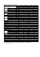
ALARM AND CONTACT
Type Unit Default Min Max Resolution
P1 Flow switch confirmation time U sec 5 0
199 1
P2 Flow switch alarm delay at pump start U sec 120 0 199 1
P3 Low pressure alarm delay at compressor start
-
up U sec 30 0 199 1
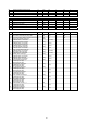
P4 Comp overload alarm reset type U Flag 0 0 1 1
0=Manual reset, 1=Auto reset
(
manual
)
P
5
High pressure alarm reset type U Flag 1 0 1 1
0=Manual reset, 1=Auto reset
(
auto
)
P6 Low pressure alarm reset t
y
pe U Fla
g
10 11
0=Manual reset, 1=Auto reset
(
auto
)
P7 Fan overload alarm reset t
yp
eUFla
g
10 11
0=Manual reset, 1=Auto reset
(
auto
)
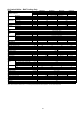
P
8
Pum
p
overload alarm reset t
yp
eUFla
g
00 11
0=Manual reset, 1=Auto reset
(
manual
)
P9 Flow switch alarm reset t
y
pe U Fla
g
00 11
0=Manual reset, 1=Auto reset
(
manual
)
P10 Auxiliar
y
alarm reset t
y
pe U Fla
g
10 11
0=Manual reset, 1=Auto reset
(
auto
)
P11 Antifreeze alarm reset t
y
pe U Fla
g
10 11
0=Manual reset, 1=Auto reset
(
auto
)
P12 Comp overload contact type U Flag 0 0 1 1
0=Normally close (NC)
1=Normall
y
o
p
en
(
NO
)
(NC)
P13 Hi
g
h pressure contact t
y
pe U Fla
g
00 11
0=Normally close (NC)
1=Normall
y
o
p
en
(
NO
)
(NC)
P14 Low
p
ressure contact t
yp
eUFla
g
00 11
0=Normally close (NC)
1=Normall
y
o
p
en
(
NO
)
(NC)
P15 Fan overload contact t
yp
eUFla
g
00 11
0=Normally close (NC)
1=Normall
y
o
p
en
(
NO
)
(NC)
P16 Pum
p
overload contact t
yp
eUFla
g
00 11
0=Normally close (NC)
1=Normall
y
o
p
en
(
NO
)
(NC)
P17 Flow switch contact t
y
pe U Fla
g
00 11
0=Normally close (NC)
1=Normall
y
o
p
en
(
NO
)
(NC)
P18 External alarm contact t
yp
eUFla
g
00 11
0=Normally close (NC)
1=Normall
y
o
p
en
(
NO
)
(NC)
P19 Defrost end contact t
yp
eUFla
g
00 11
0=Normally close (NC)
1=Normally open (NO)
(NC)
35