
Specifications


4.2 Others Configuration
x JH2 in Chiller panel should let it open (put the jumper header on one pin only) all the time unless user need to
do CMOS reset to that particular panel.
x JH3 should let it open (put the jumper header on one pin only) all the time as well.
x Remember to put in the coin cell battery on the panel. Without the backup battery, the panel will always reset
the time to 12:00am, 1st Jan 2000.
4.3 Installation of the Chiller Panel Controller
x Disconnect the unit and ensure no others unit energy source that supplies the panel.
x Open the rear panel of the Chiller Panel (insert a ‘flat-head’ screwdriver in the top joint of main casing with
rear panel to open the rear panel)
x Pass the necessary wires of the panel across the large opening in the rear panel. Place the rear panel flat
support against the wall and make marks on the wall through the four installation holes (inner or outer).
x Drill four appropriate holes in the marked places.
x Attach the rear panel to the wall and put on the screws on it. Ensure that all cables are passed through the
hole of the rear panel.
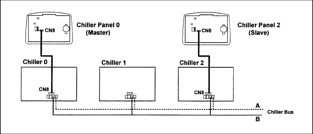
x Connect the wires to the corresponding terminal according to the wiring bus network. The power supply and
communication wires must be correctly connected to ensure that the panel works.
x Close the Chiller panel (ensure the bottom joint is aligned for the casing, then complete others joint part.
Ensure that the contacts at the back of the panel are aligned with each others)
BUS WIRING NETWORK
7