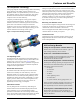
Catalog 604-3 Magnitude™ Magnetic Bearing Centrifugal Chiller Model WME 400 to 700 tons (1400 to 2461 kW) 3/60/460 HFC-134a
Note: The unit shown is for the default configuration; your unit may be configured differently. Refer to your selection for configuration.
Contents Features and Benefits . . . . . . . . . . . . . . . . . . . . . . . 4 Technology That Just Makes Sense . . . . . . . . 4 The Compressor Technology . . . . . . . . . . . . . 5 Oil-Free Design Benefits . . . . . . . . . . . . . . . . . 5 Unit Control Features. . . . . . . . . . . . . . . . . . . . 6 IPLV/NPLV Defined . . . . . . . . . . . . . . . . . . . . . 6 Quality Standards . . . . . . . . . . . . . . . . . . . . . . 7 Chiller Identification. . . . . . . . . . . . . . . . . . . . . . . . .
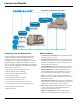
Features and Benefits Features and Benefits Magnitude™ Magnetic Bearing Chillers WME0700 WME0500 500 WMC400D Model WME WMC290D WMC250D D WMC150D D WMC145D D Model WMC WMC145S 100 For Magnitude™ model WMC, see Catalog 602 200 300 400 500 600 700 Technology That Just Makes Sense Benefit Summary The newest member of the Daikin McQuay Magnitude™ Chiller family (Model WME) takes Magnetic Bearing Centrifugal Chillers to a new level.
Features and Benefits The Compressor Technology Cutting-edge magnetic bearing technology enables outstanding energy efficiency and reliable, long-life operation. The Magnitude chiller’s exceptional efficiency is due to the direct drive magnetic bearing compressor technology. This design eliminates the friction inherent in traditional centrifugal compressors that can reduce efficiency. A digitally-controlled magnetic bearing system replaces conventional lubricated bearings.
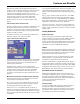
Features and Benefits Open Choices™ BAS Flexibility Integrated Variable Frequency Drives The exclusive Open Choices feature provides seamless integration and comprehensive monitoring, control, and twoway data exchange using industry standard protocols LonTalk®, BACnet™ or Modbus™. Open Choices offers simple and inexpensive flexibility to use the Building Automation System of your choice without an expensive gateway panel.
Features and Benefits By constantly monitoring chiller status and real time data, the MicroTech E controller will automatically take proactive measures to relieve abnormal conditions or shut the unit down if a fault occurs. For example, if a problem occurs in the cooling tower and discharge pressure starts to rise, the controller will automatically hold the load point and activate an alarm signal. A further rise in pressure will initiate compressor unloading in an effort to stay online.
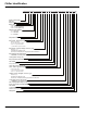
Chiller Identification Figure 3: Magnitude Code String Chiller Identification Chiller Identification WME 0500S S M2 S S AAB E3612 BE 2RA C4 440 CC Y A C3012 BYLL 2RA C4 1050 CC Y A A 134 1 2 3 4 5 6 7 8 9 10 11 12 13 14 15 16 17 18 19 20 21 22 23 24 25 Water-Cooled Chiller Unit Size Single Circuit Motor Code M2 – Standard M3 – Low THD (WME0500) M4 – Low THD (WME0700) Voltage Code, 3/60/480 A – 3/60/ 440V R – 3/ 60/460V S – 3/ 60/480V Sound Package Compressor Revision Evap: S
Chiller Identification Figure 4: Magnitude Code String Chiller Identification 080 E1 YY EAYYY MBYYYYYY YYYY YY B 1 4 B Y Y 5 1 B A 0500 U Y H Y Y Y Y 2 B 26 27 28 29 30 31 32 33 34 35 36 37 38 39 40 41 42 43 44 45 46 47 48 49 50 51 52 Delayed Start Warranty Refrigerant Warranty Future Future Future Future Extended Warranty Standard 1st Year Warranty Chiller Startup (Std on Domestic) Refrigeration Tons Unit Revision ARI/ETL/CETL Listing Standard/Certified/Witness Test Option Knockdown: Y-None 1-Type
Electrical Data Electrical Notes Electrical Data 1 Units are available for 460 or 440 to 480 VAC at 60 Hz. 2 Wiring, fuse and wire size must be in accordance with the National Electric Code (NEC). 3 Important: Voltage unbalance not to exceed 2%. Notes for field wiring diagram 1 All line-side wiring must be in accordance with the NEC and be made with copper wire and copper lugs only. 2 A customer furnished 24 to 240 Vac power for alarm relay coil may be connected at J18.
Field Wiring Diagram Figure 5: Field Wiring Diagram Field Wiring Diagram Cat 604-3 11
Dimension Drawings Drawing Notes 9 Unit shown has standard right-hand water connections. Dimension Drawings 1 All dimensions are in inches [millimeters] unless noted otherwise. 2 Final connections must allow for 0.5 inch +/- (12.7mm) manufacturing tolerances. 3 1.00-inch FPT [25.4 mm] evaporator and condenser relief valves must be piped per ANSI / ASHRAE 15. Number of relief valves is 1 per evaporator and 2 per condenser. 4 .
Dimension Drawings Figure 7: WME0500 - E3612/C3012 - 2-pass - M2 standard motor (60Hz - 440/460/480V) (See page 12 for drawing notes.) 13.7 348 LB 148.2 3764 3 RB WME0500 M2: 440V (60Hz), 460V (60Hz), 480V (60Hz) 46.9 1192 Z X 7.6 193 O.I.T.S. 3.1 80 LF 17.0 433 RF TOP VIEW 3 13.8 349 2.5 63 170.4 EVAP. (UNIT OVERALL) 4329 5, 8, 9 52.3 1327 60.5 1537 VHD HEIGHT 68.3 1734 EVAP. RELIEF VALVE 68.5 1741 UNIT CONT. BOX EVAP 96.8 2460 UNIT O/A 3 36.6 931 COND. RELIEF VALVE 5, 11,13 47.
Dimension Drawings Figure 8: WME0500 - E3612/C3012 - 2-pass - M2 Motor (50Hz 380/400/415V - 60Hz 380/575V) WWME0500 - E3012/C2612 - 2-pass - M2 motor (50Hz 380/400/460V) with Factory-mounted Harmonic Filter WME0500 - E3612/C3012 - 2-pass - M3 Low THD Motor (50Hz 380/400/415V - 60Hz 380/440/460/480/575V) (See page 12 for drawing notes.) 13.7 348 LB 148.2 3764 3 WME0500 M2: 380V (50Hz), 400V (50Hz), 415V (50Hz), 380V (60Hz), 575V (60Hz).
Dimension Drawings Figure 9: WME0500 - E3012/C2612 -2-pass, M2 standard motor (60 Hz 440/460/480V) (See page 12 for drawing notes.) 148.2 3764 13.7 348 LB 3 RB WME0500 M2: 440V (60Hz), 460V (60Hz), 480V (60Hz) 38.9 989 Z X 5.1 130 TOP VIEW 3.1 80 17.0 433 3 RF O.I.T.S. LF 48.6 1235 169.0 EVAP. UNIT OVERALL 4292 5, 8, 9 15.6 397 2.5 63 60.5 1537 VFD HEIGHT 61.1 1551 EVAP RELIEF VALVE UNIT CONT. BOX 61.8 1568 92.9 2359 UNIT O/A 3 5,11,13 32.6 829 COND RELIEF VALVES 17.
Dimension Drawings Figure 10: WME500 - E3012/C2612 - 2-pass M2 Standard motor (50Hz 380/400/415V) (60Hz 380/575V) WME500 - E3012/C2612 - 2-pass M3 Low THD motor (50Hz 380/400WME/415) (60Hz 380/440/460/480/575V) WME500 - E3012/C2612 - 2-pass M2 Standard Motor (60HZ 380/460V) with Factory-mounted Harmonic Filter (See page 12 for drawing notes.) 148.2 3764 13.7 348 LB 3 RB WME0500 M2: 380V (50Hz), 400V (50Hz), 415V (50Hz), 380V (60Hz), 575V (60Hz).
Dimension Drawings Figure 11: WME0500 - E3012/C3012 - 2 pass, M2 Standard motor (60Hz 440/460/480V, (See page 12 for drawing notes.) 148.2 3764 13.7 348 LR RB 3 WME0500 M2: 440V (60Hz), 460V (60Hz), 480V (60Hz) 43.9 1116 Z X 7.6 193 O.I.T.S. LF 3.1 80 17.0 433 RF TOP VIEW 3 49.2 1249 13.7 347 2.5 63 169.0 EVAP. UNIT OVERALL 4292 5, 8, 9 60.5 1537 VFD HEIGHT 61.8 1570 EVAP RELIEF VALVE 3 UNIT CONT. BOX EVAP 36.6 931 COND RELIEF VALVE 5,11,13 43.6 1107 COND 19.3 489 Y Y 3 X 5.
Dimension Drawings Figure 12: WME500 E3012/C3012, M2 Motor (50 Hz, 380-415V / 60Hz, 380-575V) WME500 E3012/C3012, M3 Motor (50 Hz, 400-415 / (60 Hz, 380-575V) WME500 E3012/C3012, M2 Motor with Internal Harmonic Filter (60 Hz, 380-460V) WME 18 Cat 604-3
Dimension Drawings Figure 13: Model WME0700 - E3612/C3012 - 2-pass, M4 motor, 3/4” tubes (To determine tube size, see note 17 on page 12.) LB 148.2 3764 13.7 348 RB 3 46.9 1192 4.0 101 Z O.I.T.S. 6.2 157 LF 16.8 427 TOP VIEW 3 X 77.3 1962 RF 170.4 4329 52.3 1327 13.8 349 2.5 63 EVAP. (UNIT OVERALL) 4,6,7 M4 VFD 68.3 1736 EVAP RELIEF VALVE 3 36.7 3 931 COND RELIEF VALVES 60.0 1523 VFD HEIGHT 96.3 2446 UNIT O.A. 4,9,11 UNIT CONTR. BOX EVAP. 68.5 1741 47.0 1195 19.3 489 COND. 5.
Dimension Drawings Figure 14: Model WME0700 - E3612/C3012 - 2-pass, M4 motor, 1” tubes (To determine tube size, see note 17 on page 12.) LB 13.7 348 148.2 3764 RB 3 46.9 1192 4.0 101 Z O.I.T.S. 6.2 157 LF RF 16.8 427 TOP VIEW 3 X 170.4 4329 52.3 1327 3 EVAP. 36.7 3 931 COND RELIEF VALVES 13.8 349 2.5 63 EVAP. (UNIT OVERALL) 4,6,7 M4 VFD 68.3 1736 EVAP RELIEF VALVE 60.0 1523 VFD HEIGHT 96.3 2446 UNIT O.A. 4,9,11 UNIT CONTR. BOX 68.5 1741 47.0 1195 19.3 489 COND. 5.
Dimension Drawings Figure 15: Model WME0700 - E3612/C3612 - 2-pass, M4 motor, 3/4” tubes (To determine tube size, see note 17 on page 12.) LB 13.7 348 148.2 3764 3 RB 52.9 1345 7.0 178 Z O.I.T.S. 6.2 157 LF RF TOP VIEW 16.8 427 3 X 170.4 4329 3 42.7 1084 COND RELIEF VALVES 60.0 1523 VFD HEIGHT UNIT CONTR. BOX EVAP. UNIT O.A. 4 4,6,7 M4 VFD 74.1 1882 EVAP RELIEF VALVE 79.2 2012 2.5 63 EVAP. (UNIT OVERALL) 102.3 2599 UNIT O.A. 4,9,11 74.3 1887 52.8 1341 3 22.3 565 COND. 5.
Dimension Drawings Figure 16: Model WME0700 - E3612/C3612 - 2-pass, M4 motor, 1” tubes (To determine tube size, see note 17 on page 12.) LB 13.7 348 148.2 3764 3 RB 52.9 1345 7.0 178 Z O.I.T.S. 6.2 157 LF RF TOP VIEW 16.8 427 3 X 170.4 4329 3 42.7 1084 COND RELIEF VALVES 60.0 1523 VFD HEIGHT UNIT CONTR. BOX EVAP. UNIT O.A. 4 4,6,7 M4 VFD 74.1 1882 EVAP RELIEF VALVE 79.2 2012 2.5 63 EVAP. (UNIT OVERALL) 102.3 2599 UNIT O.A. 4,9,11 74.3 1887 52.8 1341 3 22.3 565 COND. 5.
Dimension Drawings Standard Head Connection Dimensions Figure 17: Standard Dished Head Connection Dimensions (Victaulic and Flanged) EVAPORATOR DISHED HEAD SELECTION *BB NOTE: * - ADD .500 INCH FOR FLANGED CONNECTION (SEE DETAIL LOWER LEFT) *BB *GG AA AA *GG OUTLET HEAD POSITION ON OPPOSITE END OF UNIT FF TYP. AA FF TYP. OUT IN IN RIGHT END REPRESENTATIVE VIEW ( TYPICAL OF ALL STACKS WITH 2 PASS HEADS & 3/4" EVAP TUBING ) FF TYP.
Dimension Drawings Marine Water Box Dimensions Marine water boxes with removable end covers are an available option on all evaporator and condenser sizes. Figure 18: Marine Water Box Dimensions with Victaulic or Flanged Connections EVAPORATOR MARINE WATER BOX SELECTION EEE IN OUT EEE DDD CCC EEE NOTE: * - ADD .500 INCH FOR FLANGED CONNECTION (SEE DETAIL LOWER LEFT) CCC DDD IN DDD CCC DDD CCC AAA *GGG OUTLET HEAD POSITION ON OPPOSITE END OF UNIT AAA FFF TYP.
Dimension Drawings Optional External Harmonic Filter Dimensions Figure 19: Model AUHF 300, 350, 400, Free Standing, 460Volt, Harmonic Filter Cable Entry/Exit (Both Sides) Table 7: Model AUHF Dimensions from Figure 19 MODEL A B C AUHF 300-460V AUHF 350-460V AUHF 400-460V in. (mm) in. (mm) in. (mm) 26.2 (664) 32.0 (813) 32.0 (813) 25.0 (636) 29.5 (749) 29.5 (749) 45.0 (1143) 51.5 (1308) 51.5 (1308) D E F G H J K L WEIGHT 21.2 (538) 25.6 (651) 25.6 (651) 19.0 (483) 23.5 (597) 23.5 (597) 21.
Dimension Drawings Figure 20: Model ATL 300, 350, 400, Free Standing, 600Volt, Auto Transformer Harmonic Filter Cable Entry/Exit (Both Sides) Table 8: Model ATL Dimensions & Weights, 60Hz; 380V, 440V, 600V, from Figure 20 MODEL in. (mm) in. (mm) in. (mm) ATL 300 ATL 350 ATL 400 A B C D E F G H J K L WEIGHT 39.5 (1004) 44.0 (1119) 44.0 (1119) 34.1 (867) 38.0 (965) 38.0 (965) 59.0 (1499) 66.0 (1676) 66.0 (1676) 29.8 (756) 33.7 (855) 33.7 (855) 32.0 (813) 36.0 (914) 36.0 (914) 34.
Physical Data & Weights Lifting and Mounting Weights Physical Data & Weights Figure 21: Corner Identification NOTES: 1 The block shown above is the mounting footprint, not the entire unit footprint. 2 Lifting holes in the top of the tube sheets are 3.25-inch (83 mm) diameter. 3 Mounting holes in the feet are 1.125-inch diameter. 4 Weights are based on standard configuration; actual weight may vary depending on options.
Physical Data & Weights Figure 22: Lifting Points - See Installation Manual IM 1033 for handling information. Lifting Po int (Ou tside Co rner Hid den) Power Cable Entry Note: This drawing is for general reference only. VFD Power Panel Lifti ng P oint Refer to dimension drawings for location of components. Li fting Points Physical Data - Evaporator Refrigerant-side maximum working pressure is 200psig. Water-side is 150 psi (1034 kPa) with 300 psi (2068 kPa) available as an option.
T Cat 604-3 = High Pressure Switch = Temperature Sensor = Pressure Sensor = Reference number T P 1 1 Strainer HPS 6 Phase configuration shown.
Application Considerations Location Requirements Application Considerations Daikin McQuay Magnitude units are designed only for indoor, weather-protected, non-freezing area consistent with the NEMA 1 rating on the chiller, controls, and electrical panels. Equipment room temperature for operating and standby conditions is 40°F to 104°F (4.4°C to 40°C). Optimum Water Temperatures and Flow A key to improving energy efficiency for any chiller is minimizing the compressor pressure lift.
Application Considerations Condenser Water Temperature When the ambient wet bulb temperature is lower than design, the entering condenser water temperature of Magnitude WME chillers can be lowered to improve chiller performance. Chillers can start with entering condenser water temperatures as low as 40°F (4.4°C). For short periods of time during startup, the entering condenser water temperature can even be lower than the leaving chilled water temperature.
Application Considerations Include thermometers and pressure gauges at the chiller inlet and outlet connections and install air vents at the high points of piping. Where noise and vibration are critical and the unit is mounted on spring isolators, flexible piping and conduit connections are necessary. Variable Fluid Flow Rates and Tube Velocities Many chiller system control and energy optimization strategies require significant changes in evaporator and condenser water flow rates.
Options and Accessories Unit Options Single insulation - evaporator shell / heads / suction piping Export packaging 0.75-inch insulation on cold surfaces. Insulation, either optional factory-installed or field-installed is required on all installations. Options and Accessories Can be either open or closed crate and with optional shipping bag. A wooden skid and a shrink-wrapped bag covering the entire unit and protecting it from possible dirt and grime accumulation during transit are standard.
Options and Accessories 2 Special corrosion inhibiting coatings on any "wetted surface" including tubesheets, heads (compact water boxes), marine water boxes, or nozzles 3 Clad tube sheets 4 Sacrificial anodes in heads (compact water boxes) or marine water boxes 5 Eddy current testing and report used to verify baseline tube condition 6 Special NEMA enclosures 7 Davits or hinges for marine water box covers or heads (compact water boxes) 9 Spacer rings on heads to accommodate automatic tube 10 Brush clea
Engineering Guide Specifications Engineering Guide Specifications SECTION 15XXX: MAGNETIC BEARING CENTRIFUGAL CHILLERS PART 1 - GENERAL 1.1 SUMMARY A Section includes design, performance criteria, refrigerants, controls, and installation requirements for water-cooled centrifugal chillers. 1.2 REFERENCES A Comply with the following codes and standards: • AHRI 550/590 • AHRI 575 • NEC • ANSI/ASHRAE 15 • OSHA as adopted by the State • ETL • ASME Section VIII 1.
Engineering Guide Specifications entire unit, for a period of one year from equipment startup or 18 months from shipment, whichever occurs first.
Engineering Guide Specifications include overall dBA. Data shall be the highest levels recorded at all load points. Octave Band 63 125 250 500 1000 2000 4000 8000 Overall dBA and stamped according to the requirements of the ASME Code, Section VIII. The tubes shall be individually replaceable and secured to the intermediate supports without rolling. 2 The evaporator shall be flooded type with [0.025 in.] OR 2.
Engineering Guide Specifications B Vibrations 1 Provide neoprene waffle-type vibration isolators for each corner of the unit. C Unit shall be bagged and mounted on skids for shipment. D Power Connections • Power connection shall be single point to a factorymounted disconnect switch OR shall be multipoint to each compressor power panel on two-compressor units.
Engineering Guide Specifications chiller shall meet a minimum seismic design spectral response acceleration of 1.60 SDS. The chiller must be mounted to a rigid base and may use neoprene waffle vibration pads. 6 Certified performance test in accordance with procedures and to the tolerances contained in AHRI Standard 550/ 590. -- OR -6 Witness performance test in accordance with procedures and to the tolerances contained in AHRI Standard 550/ 590. PART 3 - EXECUTION 3.
Engineering Guide Specifications 40 Cat 604-3
McQuay Training and Development Now that you have made an investment in modern, efficient Daikin McQuay equipment, its care should be a high priority. For training information on all Daikin McQuay HVAC products, please visit www.daikinmcquay.com and click on training, or call 540-248-9646 to speak with the Training Department. Warranty All Daikin McQuay equipment is sold pursuant to its standard terms and conditions of sale, including Limited Product Warranty.