Engineered for flexibility and performance.
c 2004 McQuay International. All Rights Reserved. is a registered trademark of McQuay in the United States and other countries, licensed and recognized all over the world. Without prior written consent of McQuay, use of the above-named trademark for business purposes may constitute a violation of the federal and state laws in the Unites states and laws of related countries, and remain subject to a charge of trademark infringement and unfair competition.
CONTENTS 1. Overview 1.1 General Information ......................................................................................................... 4 1.2 Working Principle & System Principle .............................................................................. 4 1.3 Main Features ................................................................................................................ 10 1.4 Nomenclature ......................................................................................
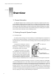
Design & installation Guide For McQuay MDS Multi System C H A P T E R 1 Overview 1.1 General Information The MDS(Multi Digital Scroll) air conditioning system is operated by a digital compressor and is accommodated by multiple evaporators (indoor units). It is touted as the next-generation modular system in the world of high-efficiency air conditioning. lt has undoubtedly changed the face of cooling associated with high-storied buildings.
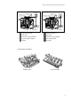
Design & installation Guide For McQuay MDS Multi System Discharge pressure Solenoid valve Modulation chamber Discharge pressure Solenoid valve Modulation chamber Bleed hole Loading Suction pressure Bleed hole Unloading PWM valve power off PWM valve power on Valve close Valve open Suction pressure Fixed scroll move downwards Fixed scroll moves upwards Two scrolls gather together Two scrolls separate Loading Unloading 1.2.
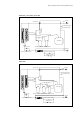
Design & installation Guide For McQuay MDS Multi System 1.2.3 Diagram of the Unit System MDS030A MDS040A MDS050A MDS060A Filter Indoor unit 1 Outdoor heat exchanger HPS Outdoor Filter LPS Electronic expansion valve Digital compressor PWM Liquid receiver Filter Indoor unit n Accumulator indoor Filter Dry filter Electronic expansion valve Note: The MDS030A unit excludes the reservoir.
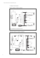
Design & installation Guide For McQuay MDS Multi System MDS080BR MDS100BR MDS120BR Ball valve Four-way valve Filter Pressure tapping point Oil separator Low pressure sensor High pressure switch Pressure tapping point Heat exchanger Check valve Accumulator Check valve Standard compressor Digital compressor Ball valve Filter Electronic expansion valve Electronic expansion valve Capillary Dry filter MDS150BR Ball valve Four-way valve Filter Pressure tapping point High pressure sensor High
Design & installation Guide For McQuay MDS Multi System MDS180BR Check valve Filter Filter High pressure sensor High pressure switch Ball valve Pressure tapping point Low pressure sensor Heat exchanger Pressure tapping point Oil separator Four-way valve Heat exchanger Four-way valve Ball valve Check valve Electronic expansion valve Accumulator Check valve Standard compressor Standard compressor Digital compressor Filter Ball valve Electronic expansion valve Capillary Dry filter MDS200B
Design & installation Guide For McQuay MDS Multi System MDS260BR Master unit Filter Ball valve Four-way valve Pressure tapping point Check valve Oil separator Low pressure sensor High pressure sensor High pressure switch Heat exchanger Pressure tapping point Check valve Accumulator Ball valve Standard compressor Digital compressor Filter Electronic expansion valve Ball valve Electronic expansion valve Capillary Dry filter Filter Ball valve Four-way valve Slave unit Pressure tapping point
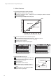
Design & installation Guide For McQuay MDS Multi System 1.3 Main Features 1.3.1 Wide Range and Stepless Capacity Modulation Wide capacity modulation range 10%-100%) According to changing the ratio of loading time and unloading time, MDS can modulate Running ratio of compressors(%) the capacity steplessly Lower the energy consumption and running cost. 100% MDS system Inverter system Total capacity of operating indoor units(%) 1.3.2 Accurate Temperature Control and Quick Response.
Design & installation Guide For McQuay MDS Multi System 1.3.4 Energy Saving The inverter system capacity modulation range is from 30% to 100%, while MDS system capacity modulation range is from 10% to 100%; Quick response to the capacity modulation; Min. power consumption is only 10% of the full load power consumption; Compared to the inverter system, there is no power consumption of transducer; Compared to the nominal capacity scroll system, it can save 20% energy consumption.
Design & installation Guide For McQuay MDS Multi System 1.3.7 Space Saving Compared to traditional central air conditioning, MDS system is higher centralized, no need for special equipment room to save more space, and bring more benefits. Traditional central air conditioning MDS system 1.3.8 Easy to Install and Simple to Maintain Easy installation MDS system is simple, and the pipe layout is clear.
Design & installation Guide For McQuay MDS Multi System Indoor unit: ceiling concealed unit M CC 050 T -R (B)/(D)- A M A McQuay Ceiling concealed indoor unit Cooling capacity No. Design serial No. Design alternation No.
Design & installation Guide For McQuay MDS Multi System Indoor unit: Wall Mounted Indoor Units M WM 015 T - A M A Design alternation No. Matching outdoor units: MDS series Power supply features: A:220V /50Hz Design serial No. Cooling capacity No. Indoor unit: Wall Mounted Indoor Units McQuay Outdoor unit: MDS unit MDS 060 A R - F AA Description of the unit Power supply: A:220V /50Hz B:380V/3N /50Hz Heat pump (omitted if cooling only) Design serial No. Cooling capacity No.
Design & installation Guide For McQuay MDS Multi System 1.5.2 Indoor Products Model 0.8HP 1.0HP 1.5HP 1.8HP Capacity range 2.0HP 2.5HP 3.0HP 4.0HP 5.0HP 6.0HP MCC MCK MCM MDB MWM 1.6 Performance Parameter 1.6.
Design & installation Guide For McQuay MDS Multi System 1.6.
Design & installation Guide For McQuay MDS Multi System 1.6.6 MDS-A Specification(Outdoor Unit) Model Unit Nominal cooling capacity kW MDS030A MDS030AR MDS040A 8.5 8.5 10 MDS040AR MDS050A 10 12.5 12.5 14.5 14.5 Nominal heating capacity kW - 9.0 - 11.5 - 13.5 - 16.5 Dimension (L x W x H) mm 840x408x900 Weight kg 82 Cooling rated power input kW 3.0 3.0 A 13.6 13.6 kW - 2.5 A - 11.
Design & installation Guide For McQuay MDS Multi System 1.6.7 MDS-B Specification (Outdoor Unit) MDS Model MDS MDS MDS MDS MDS MDS MDS MDS MDS MDS Nominal cooling capacity kW 24.5 24.5 28.0 28.0 32.5 32.5 40.0 40.0 47.5 47.5 50.0 50.0 Nominal heating capacity kW - 26.0 - 30.0 - 34.0 - 43.0 - 50.0 - 53.
Design & installation Guide For McQuay MDS Multi System 1.7 Operating Range Note The table is gotten based on the equivalent length of 16m and the height is 0 m. 1.8 Refnet 1.8.1 Y Type Unit mm Length(mm) Refnet model A B C Diameter D E(outer diameter F (mm) G Diameter H I(outer diameter J K (mm) L Diameter M N(outer diameter O (mm) P Q MDS-Y1 553 172 293 120 28.6 28.9 25.7 22.5 28.6 28.9 25.7 22.5 19.3 22.2 MDS-Y2 420 142 223 80 15.88 16.1 12.9 9.7 12.7 12.9 9.7 6.
Design & installation Guide For McQuay MDS Multi System Type: MDS-Y5 Unit: mm 1.8.
Design & installation Guide For McQuay MDS Multi System Type: MDS-C2/C3 80 80 80 OD ͺ9.7 OD ͺ12.9 OD ͺ16.1 204 Four places of silver & copper brazed A B C E D OD ͺ19.3 250 550 Refnet joint type Refnet joint type ͺ(mm) A(outer diameter) B C D MDS-C2 28.6 28.9 25.7 22.5 19.5 MDS-C3 25.4 25.7 22.5 19.3 16.1 E Unit: mm 1.9 Outline of Indoor Units 050T H E L T J G F C A B D K 1.9.
Design & installation Guide For McQuay MDS Multi System 1.9.2 MDB050T 995 957 702 340 823 6-11.5x20 998 1032 1063 910 57 302 80 173 177 286 350 823 1230 Unit: mm 1.9.3 MDB060T 1195 1157 823 340 702 6-11.
Design & installation Guide For McQuay MDS Multi System 1.9.4 MCC008 010 015 018 020 025 030 040 050 060T 37 187 52 D A B C G J 151 F 75 F 1 47 20 141 253 Unit: mm Model MCC008T MCC010T MCC015T MCC018T MCC020T MCC025T MCC030T MCC040T MCC050T MCC060T A 690 690 690 950 950 950 950 1300 1300 1560 1.9.
Design & installation Guide For McQuay MDS Multi System 1.9.6 Auxiliary Heating Coil D 41 32 237 119 32 143 221 97 167 Water outlet Rc3/4 taper pipe threads Water inlet 15 15 A 33 B 33 37 15 163 long hole for Mounting 4 - 10ġ20 Unit: mm Model A B C D HWT08-15 762 704 732 818 HWT18-30 1022 964 992 1078 HWT40-50 1372 1314 1342 1438 HWT60 1632 1574 1602 1688 1.9.
Design & installation Guide For McQuay MDS Multi System 1.10 Outline of Outdoor Units 1.10.1 MDS030A(R) 840 590 124 240 330 408 378 125 4-12x18 460 900 318 20 60 67 50 1.10.
Design & installation Guide For McQuay MDS Multi System MDS120B(R) 8-14x20 screw hole (for setting) Amplify here A-A 14 MDS150B(R) 16 1.10.3 MDS080B(R) MDS100B(R) A 877 840 845 20 170 A-A 45 Unit: mm 1840 1575 265 B Model MDS080B(R) MDS100B(R) MDS120B(R) MDS150B(R) A 900 900 900 1200 B 990 990 990 1290 539 1.10.
Design & installation Guide For McQuay MDS Multi System C H A P T E R 2 Unit Control 2.1 Introduction to the Controller MDS system is controlled by the micro-computer. Several types of controller are available, including wireless controller, wire controller, wire controller + remote controller and central controller. One wireless controller can control one unit, one wire controller can control one unit or up to 48 units, while central controller can control up to 1536 units (32 groups). 2.
Design & installation Guide For McQuay MDS Multi System 2.3 Operation of the Controller 2.3.1 Main Features Both wired controller (using the key on board) and remote controller (equipped with infrared receiver to receive the order from the remote controller ) to control the unit, and to perform such functions as parameter setting, working mode setting, status display and malfunction indicating.
Design & installation Guide For McQuay MDS Multi System Temp unit setting There is a switch on the PCB board. When switch OP1 is ON, the unit is ; when it is OFF, the unit is oF.Alternate method is as follows: Press fan key and last for 5 seconds in the normal condition, the temp unit setting will be successful and there will be a buzzer to indicate. Real time setting Press CLK to enter, the first time is week setting and indicate its icon, press or to adjust the week from Sunday to Saturday.
Design & installation Guide For McQuay MDS Multi System Timer setting Press Timer to enter timer setting (When the unit is ON, it can only be set to OFF; When the unit isOFF , it can only be set to ON) and last timer will be shown on the LCD. If there is no press on any key within 5 seconds, it will exit and cancel the timer setting at to increase the hour while the same time. During this 5 seconds, press press to increase the minutes, please press Timer within 5 seconds to confirm the setting.
Design & installation Guide For McQuay MDS Multi System 2.3.3 Wire Control Panel Fan ON/OFF Fan ON/OFF Fan ON/OFF Fan ON/OFF Fan ON/OFF Temp. Temp. Temp. Temp. Temp.
Design & installation Guide For McQuay MDS Multi System 2.4 Software Management System 2.4.1 Real-time Monitor Software System monitoring software: The real-time MDS unit monitoring software features powerful functions, including indoor monitoring, system monitoring, loop monitoring and service monitoring. With it, the user or service debugging personnel can view detailed unit parameters and have a deep understanding of the unit operation.
Design & installation Guide For McQuay MDS Multi System Loop monitoring* Select and view the outdoor unit s system Service monitoring* Display the current operation parameters figure, operation parameters and the operation parameters of all indoor units. and history record curve of indoor/outdoor unit in the system. Note: Only the authorized maintenance personnel can operate on this interface 2.4.
Design & installation Guide For McQuay MDS Multi System 2.5 Network Central Control One outdoor unit can be connected with maximum 48 indoor units.Control over up to 32 outdoor units can be realized by a centralized controller, and the monitoring software monitors up to 1536 (32x48) units simultaneously in real time.The cabling of outdoor and indoor units is simple.The MDS system features powerful fault display and query function greatly saving the maintenance time and costs.
Design & installation Guide For McQuay MDS Multi System 2.6 Wiring Diagram 2.6.
Design & installation Guide For McQuay MDS Multi System Model MCK025/030/040/050T SW-PB KEY1 JP7 J1 J5 J4 HF MF LF J3 LINE J2 MOTOR B CON5 A J6 EXV CON3 CON2 L ON 1 blue N N N SW3 ON 2 3 SW1 DIP 4 SW2 DIP 5 ON 6 3 4 5 6 7 2 2 3 4 5 6 DIP CON9 ROOM 8 1 CON4 red JP5 JP3 JP4 1 Connecting indoor/ outdoor units communication NEUTRAL JP2 JP1 JP6 OUTID2 WATER CON6 TR1 TR2 red blue black yellow/green M ~ Swing motor Drainage pump Remote receiving M ~ b
Design & installation Guide For McQuay MDS Multi System Model MCM050T SW-PB KEY1 JP7 J1 J5 J4 HF MF LF J3 LINE J2 blue N L N LF MF HF SW3 ON 2 3 SW1 DIP SW2 4 ON 6 CON2 DIP 5 ON 2 3 4 5 6 7 1 3 4 5 6 blue red yellow/green Fan motor 1 black M ~ M ~ Fan motor 2 Fan motor 3 Indicator (220V~/50Hz) Notes: 1.Set jumper JP:For JP1,upper two are set to OFF,the lower two to ON,and other JPs are set to OFF. 2.SW2 sets this unit address. 3.
Design & installation Guide For McQuay MDS Multi System 2.6.
Design & installation Guide For McQuay MDS Multi System Model MDS040A 220V~/50Hz N 2 PWMV KM 5 4WV 1L1 3L2 5L3 8 10 LOW-FAN FIXED COMP 7 DIG COMP PWMV 3 HI-FAN FU MID-FAN N L KM LIVE 2T1 4T2 6T3 RY1 RY2 RY4 RY3 RY5 RY6 RY7 NEUTRAL J2 brown yellow blue orange brown yellow blue orange N NEUTRAL blue blue TRAN-H 14 red white red OV-COMP1 Fan 2 Fan 1 Compressor OV-COMP2 J1 JP1 LP 11 LP HP 12 HP JP2 GND DLT A B AI-IN MidLet 13 McQuay TRAN-L M ~ Out
Design & installation Guide For McQuay MDS Multi System Model MDS050A 220V~/50Hz N 2 PWMV KM 5 DIG COMP 1L1 3L2 5L3 8 10 LOW-FAN 7 FIXED COMP 4WV PWMV 3 HI-FAN FU MID-FAN N L KM LIVE 2T1 4T2 6T3 RY1 OV-COMP1 J1 LP 11 LP HP 12 HP Fan 2 JP2 GND DLT A B AI-IN MidLet JP1 Connecting indoor unit communication Description of components and parts: Coil middle temperature sensor(TH5) Jumper settingsǖ DIP switch J2 setting: Symbol Description Symbol PTC Compressor start-up unit
Design & installation Guide For McQuay MDS Multi System Model MDS050AR(380V/3N~/50Hz) N R S T DB3A L 71 81 red green yellow FU T KM L1 LIVE N NEUTRAL RY1 RY2 22 RY4 RY3 23 LOW-FAN HI-FAN MID-FAN 4WV PWMV KM OL 21 3 2 1 DIG COMP 71 4WV N 81 PWMV FIXED COMP R S RC EXV DB3A RY5 RY6 RY7 brown yellow blue orange brown yellow blue orange red green yellow J2 NEUTRAL TRAN-H Transformer T2 T1 T3 M ~ Shaft heater M ~ C1 OV-COMP2 TRAN-L M ~ C2 OV-C
Design & installation Guide For McQuay MDS Multi System Model MDS060AR(220V~/50Hz) N N L 2 FU 19 K3 18 K2 17 K1 RC K2 5 1L1 3L2 5L3 21 K3 7 HI-FAN DIG COMP 4WV PWMV K1 KM 4 3 8 10 LOW-FAN 4WV MID-FAN PWMV FIXED COMP EXV KM LIVE 2T1 4T2 6T3 22 RY1 RY2 Fan 1 C3 black red OV-COMP2 OV-COMP1 J1 Fan 2 GND DLT A B AI-IN Description of components and parts: Symbol Description Symbol PTC Compressor start-up unit 4WV Four-way valve FU Contactor PWMV C1-2 Capac
Design & installation Guide For McQuay MDS Multi System V1+ V1V2+ V2- S1 HP N L J18 J1 1 2 4 KM3 KM4 3 5 KM4 PMW Symbol Description Symbol DB3A Phase-loss/reverse protector FU Fuse Overload protection settings : Model OL1 OL2 OL3 MDS080B 11.6A 14.0A 1.9A MDS100B 14.0A 14.0A 1.9A MDS120B 14.0A 14.0A 3.
Design & installation Guide For McQuay MDS Multi System WHITE RED WHITE BLACK RED WHITE BLACK FIX3-OL FIX2-OL T2 WHITE M ~ S1 HP N L J18 J1 Constant-speed compressor 2 Digital compressor Connecting the indoor unit 32 Connecting central control system 33 S2 S3 EXV1 1 Constant-speed compressor 1 31 DIG-OL LP HP 15 OL4 16 OL5 17 L1 MDS-P FIX1-OL OL3 14 BLACK BROWN RED BLUE T2 T3 M ~ T1 YELLOW RED BLUE YELLOW BLUE T2 T1 M T3 ~ T3 M ~ OL1 13 24 25 26 30 DIG T1 RED YELLO
Design & installation Guide For McQuay MDS Multi System N R ST L FU TR KM4 KM5 KM6 KM7 OL3 OL4 OL5 OL6 OL7 HPT 1 2 3 TH6 TH3 TH11 TH9 TH4 TH1 TH7 TH5 TH12 TH10 TH8 TH2 LOW-U HI-U FIX2-OL FIX1-OL DIG-OL LP FIX3-OL OL2 12 OL1 13 OL3 14 MDS-E MDS-M Bpc Apc Bin Ain KM3 OL2 V2EXV3 EXV2 KM2 HI-1 V1- LPT 1 2 3 V2+ FANH1 FANL1 KM1 OL1 LOW-I V1+ BLACK WHITE FANH2 FANL2 FANH3 FANL3 SV1 SV2 L RED YELLOW BLUE T 71 S 81 R N DB3A RED WHITE BLACK RED WHITE BLACK 380V/3N~/50Hz Air di
Design & installation Guide For McQuay MDS Multi System OL3 11 FIX3-OL OL2 12 FIX2-OL OL1 13 T2 M ~ T1 T3 T2 M ~ T3 T1 T2 M ~ T1 T3 T2 T3 M ~ DIG-OL LP HP 15 OL5 16 OL6 17 S1 BROWN WHITE BLACK OL7 18 OL8 19 J1 HP N L M ~ Fan motor 1 Fan motor 2 Description of components and parts : Symbol Description Symbol FU DB3A Phase-loss/reverse protector 4WV Four-way valve KM Contactor HP High-pressure switch LPT HPT TR Low -pressure sensor High-pressure sensor Transformer Overlo
Design & installation Guide For McQuay MDS Multi System HP 15 OL3 16 OL4 17 M ~ J1 Shaft heater HP N L S1 Connecting central control system 33 S2 S3 EXV1 EXV4 EXV1 EXV4 J18 Shaft heater 1 2 7 4 10 11 KM3 KM4 Digital compressor Constant-speed compressor RED WHITE BLACK Coil inlet temperature sensor TH2 Air discharge temperature sensor of the digital compressor TH1 Bpc Apc Bin Ain 32 DIG-OL LP L1 Connecting the indoor unit 31 DIG WHITE BLACK BROWN RED BLUE T2 T3 M ~ MDS-P
Design & installation Guide For McQuay MDS Multi System WHITE FIX3-OL FIX2-OL OL2 12 19 20 T2 T1 T3 M ~ T2 T1 T3 M ~ FIX1-OL 24 25 26 OL3 14 BROWN WHITE BLACK RED BLUE YELLOW 21 22 23 T2 T1 T3 M ~ Shaft heater Shaft heater OL1 13 RED YELLOW BLUE RED YELLOW BLUE RED YELLOW BLUE 18 MDS-P DIG-OL LP HP 15 OL4 16 OL5 17 L1 M ~ J1 HP N L S1 compressor 2 2 compressor 3 Fan motor 3 KM5 Description of components and parts : Symbol -48- Description Symbol Description DB3A Phase-lo
Design & installation Guide For McQuay MDS Multi System 2.7 Electric Connection 2.7.
Design & installation Guide For McQuay MDS Multi System 2.7.
Design & installation Guide For McQuay MDS Multi System 2.8 Electric Data 2.8.1 Outdoor Unit MDS Model MDS030A/ MDS040A/ MDS050A/ MDS060A/ MDS050A/ MDS060A/ MDS030AR MDS040AR MDS050AR MDS060AR MDS050AR MDS060AR 380V /3N /50Hz Power supply 220V /50Hz 2 6(2.5) 4(2.5) Power Cross section area(mm ) cable Q.T.Y 2(1) 4(1) Model MDS080B/ MDS080BR MDS100B/ MDS100BR Power supply Power Cross section area(mm2) cable Q.T.
Design & installation Guide For McQuay MDS Multi System C H A P T E R 3 Selection 3.1 Load Calculation 3.1.1 Planning and Cooperation McQuay recommends you to estimate and plan the following before engineering. Based on the air conditioning area function, calculate cooling/heating load (depending on the temperature,humidity, and ventilation).
Design & installation Guide For McQuay MDS Multi System If we know the heat performance index qv[W/(m3 . calculate the heating load )] and outside volume V (m3), we can as follows: Qtotal = aqvV( tn tw) Where, a is the correction factor. For details, see the table. qv is the heat performance index of the building. It is the heating load when the difference between the indoor temperature and the outdoor temperature is 1 . For details, see the table. V is the outside volume of the building.
Design & installation Guide For McQuay MDS Multi System 3.2 Selection of Indoor Units The selection of indoor unit should be based on the several factors, including customer s requirement, indoor air distribution, indoor decoration, etc. Ceiling concealed, ceiling cassette, high pressure duct unit and ceiling exposed are available now. The indoor unit should be selected to meet the actual indoor load demand. The nominal cooling capacity should be is more than or equal to the actual indoor load demand.
Design & installation Guide For McQuay MDS Multi System 3.3 Selection of Outdoor Units For the allowed combinations, please refer to the "Total Capacity Indexes of a Combination of Indoor Units" table. The standard combination is the one with which the total indoor unit capacity is most proximate to but less than 100% of the capacity of the outdoor unit combination. 3.3.
Design & installation Guide For McQuay MDS Multi System 3.3.7 Actual Capacity Calculation Based on the model and combination rate of the outdoor unit, select an appropriate door unit capacity table. Then find out the capacity of the outdoor unit (kW) and that of each indoor unit (kW) according to the related temperatures of the indoor and outdoor units.The formula is as follows: IUC=OUC x (INX/T NX) Where, IUC is the actual capacity of each indoor unit. OUC is the capacity of the outdoor unit. unit: kW.
Design & installation Guide For McQuay MDS Multi System 3.3.10 Temperature-related Cooling Capacity Correction Factors 3.3.11 Temperature-related Heating Capacity Correction Factors 27 18 1.10 1.15 1.05 20 Corre ction facto r 1.00 0.90 0.70 0.95 22 0.80 0.65 24 0.
Design & installation Guide For McQuay MDS Multi System 3.4 Design of Air System The air cooled pipeline unit is an important and complex part of the air system. The air system must be designed in compliance with Design Code for Heating, Ventilation and Air Conditioning and Code of Design on Building Fire Protection.
Design & installation Guide For McQuay MDS Multi System The conflux of the return air inlet brings little affect on the air flow pattern in the room. So, its structure is simple. Some only have a metal mesh in the orifice, or a shutter or grille. The return air inlet location and shape depend on the air flow pattern. If it is installed in the lower area of the room, the lower edge of the inlet must be at least 0.15 m away from the ground.
Design & installation Guide For McQuay MDS Multi System Select the loop with most resistance and that with minimum resistance, and then calculate the frictional resistance and local resistance loss of each pipe segment. Check the unbalance ratio of the loop of most resistance to that of minimum resistance must be less than 15%. Otherwise, redesign the air pipe system, or satisfy the balance ratio requirements by adjusting with the valve. 3.4.
Design & installation Guide For McQuay MDS Multi System Wall thickness of the air pipe The wall thickness directly relates to the effect and life of the pipe.Too thin wall will cause unstable installation, and thus the pipe will heavily with noise increased. Even worse, the friction might compound the problem, shortening the service life of the air pipe or even the entire air conditioning system.
Design & installation Guide For McQuay MDS Multi System Acceptable (CO2) density Room type Acceptable CO2 density L/m3 g/kg Place where people stay for a long time 1 1.5 Place where children and patients stay 0.7 1.0 Place where people stay regularly (government agency) 1.25 1.75 2 3.0 Place where people stay for a short time In actual practice, the fresh air volume is generally 30m 2/h person or more, no matter how much room space a person occupies.
Design & installation Guide For McQuay MDS Multi System 3.5 Slection of Refnet Joint 3.5.1 Copper Pipe Selection ( MDS100BR ) Diameter of the main pipe and that of the remotest pipe(equivalent length<90m) Main pipe: 12.7/ 28.6(the same as the outdoor unit The remotest pipe: the same as the indoor unit Refer to the refrigerant pipe to calculate the cooling capacity of downstream A A-B-C: 17.4 kW A-D-E: 11.8 kW Select the pipe diameter of downstream A Diameter of A-B: 12.7/ 25.4 Diameter of A-D: 9.
Design & installation Guide For McQuay MDS Multi System The following tables show the refrigerant copper pipe dimension specifications. For MDS-A series Outdoor unit capacit Specification 3.0HP 4.0HP/5.0HP 6.0HP Between the outdoor unit and the first tap joint Liquid pipe 9.52mmxt0.8 9.52mmxt0.8 9.52mmxt0.8 Gas pipe 15.88mmxt1.2 19.05mmxt1.2 19.05mmxt1.2 Between the tap joints Liquid pipe Total capacity of the indoor unit to which the pipe is connected. 9.52mm x t0.8 <16kW 16kW 22.5kW >22.
Design & installation Guide For McQuay MDS Multi System Refnet joint type selection Y type Unit: mm Refnet joint type Length (mm) A B C Diameter D E(outer diameter) F (mm) G Diameter I(outer H diameter) J K (mm) L Diameter M N(outer diameter) O (mm) P Q MDS-Y1 553 172 293 120 28.6 28.9 25.7 22.5 28.6 28.9 25.7 22.5 19.3 22.2 19.3 16.1 12.9 MDS-Y2 420 142 223 80 15.88 16.1 12.9 9.7 12.7 12.9 9.7 6.5 12.7 12.9 9.7 6.5 15.88 16.1 12.9 9.7 19.1 19.3 16.1 12.
Design & installation Guide For McQuay MDS Multi System Type : MDS-C1 Unit: mm Type MDS-C2 MDS-C3 80 80 80 OD ͺ9.7 OD ͺ12.9 OD ͺ16.1 204 Four places of silver & copper brazed A B C D E OD ͺ19.3 250 550 Refnet joint type Refnet joint type ͺ(mm) A(outer diameter) B C D MDS-C2 28.6 28.9 25.7 22.5 19.5 MDS-C3 25.4 25.7 22.5 19.3 16.1 E Unit: mm 3.6 Selection of E-EXV Box To reduce the noise of indoor unit, MDS system is using external EXV Box.
Design & installation Guide For McQuay MDS Multi System C H A P T E R Installation 4.1 Outdoor Unit Installation To choose location of installation To ensure good cooling and heating performance of the units, follow up the below to pick up right place to install units: To avoid discharged air returns to the air inlet, to avoid hot air discharged by other units; ensure enough space for maintenance. To remove any barrier of air ventilation both air supply and air discharge.
FRONT FRONT BACK BACK Ľ600mm Ľ450mm FRONT BACK FRONT FRONT FRONT FRONT BACK BACK Ľ 900mm FRONT BACK Ľ450mm BACK Ľ900mm BACK ¡ 450mm Design & installation Guide For McQuay MDS Multi System Handling outdoor units Please refer to the followings to move units; To use 4 supporting points to move units instead of 3 points, to avoid unstable move and units drop off. Suspension ropes (2 ropes) Protective pads ă < 40 ă <40 >8 m >8m Notes: Be careful in the moving of outdoor units.
Design & installation Guide For McQuay MDS Multi System Installation of the Combined Outdoor Units (Suitable for Model of MDS260/280/300) Two outdoor units can be grouped as one outdoor unit, to connect with indoor units. The installation of combined units is more complicated than that of the single outdoor unit; please read the below notes carefully before installation, and strictly follow the installation instructions.
Design & installation Guide For McQuay MDS Multi System Balance pipe connection Balance pipe must be installed. Balance pipe shall be connected through the hole of side panel or base panel or the position with the other outdoor unit. Balance pipe shall be installed horizontally and orderly, and shall be lower than the access valve for balance pipe. Protect the balance pipe carefully and avoid touching any other parts, especially need to keep the pipe from touching the wall of hole.
Design & installation Guide For McQuay MDS Multi System Wall or ceiling shall be strong enough to support indoor units. Otherwise, it may cause the unit falling off. Do not expose to sunshine. Do not install units to the place where steam or oil smoke exists. Do not install units to the place where burning gas leakage may happen. Do not install around the high frequency equipment (such as high frequency electric welding machine). Do not install units in the place where acid liquid exists.
Design & installation Guide For McQuay MDS Multi System Duct Working Installation Air supply duct working installation Two types of air supply duct working: round and rectangle. Round air duct working can be connected up to the air supply inlet directly; while the rectangle one needs to be connected with a transition air duct to air supply inlet, and separate to the air diffuser. Pick up the selected air distributor or diffuser to meet the application requirements.
Design & installation Guide For McQuay MDS Multi System h. To adjust distance between the bottom panel and ceiling to 35.0mm. i. To check whether the installation is horizontal, and indoor units are fixed tightly without dropping off and vibration. Steeve nut indoor unit (drill hole in ceiling) 890.0mm washer 790.0 ceiling 35mm washer 620.4 (machine dimension) 820mm (drill hole in ceiling) 890.
Design & installation Guide For McQuay MDS Multi System There are also the hole for fresh air and exhaust air for connection with outside in indoor unit, but as for air piping, and only be the other side of refrigerant piping connector. If the indoor unit is installed to the place with a barrier (such as a head lamp) or a small space, the connecting pipe can improve air supply to two rooms at one time.
Design & installation Guide For McQuay MDS Multi System Installation of MDB-T series indoor unit To mount the MDS050~060T in ceiling. As the air outlet flange is close to the unit bottom, when the unit is mounted in ceiling, the pipe can be laid out easier, effectively reducing the requirement for room height. After the installation, only the air inlet/outlet is exposed, as shown below.
Design & installation Guide For McQuay MDS Multi System Installation of MCM-T Series Indoor Unit To Check the Accessories are Ready To install the indoor unit There are two types of installation. Make sure the hook can bear the unit weight in ceiling mounting; a slope for the drainage direction is a must both for ceiling/floor standing mounting; ensure there is enough space for maintenance around the unit.
Design & installation Guide For McQuay MDS Multi System 2. To fix the suspending panel with screw bolt as shown as above right figure. 3.
Design & installation Guide For McQuay MDS Multi System 4.3 Refrigerant Piping Design and Installation 4.3.1 Refrigerant Piping Design ( Including Selection of Refnet Joint ) Capacity combination The indoor units & outdoor units should have a relationship as follows: indoor units' cap 50% 130% outdoor units' cap Note:We strongly recommend that the capacity modulation equals to 100%.
Design & installation Guide For McQuay MDS Multi System Equivalent length Equivalent length = actual pipe length + number of elbows X equivalent length of each elbow + number of oil traps X equivalent length of each oil trap. Item Diameter elbow(m) oil trap(m) 9.52 0.18 1.3 12.70 0.20 1.5 15.88 0.25 2.0 19.02 0.35 2.4 22.02 0.40 3.0 25.40 0.45 3.4 28.58 0.50 3.7 31.80-41.30 0.55 4.0 For example: when 10HP outdoor unit's actual length is 80m, the piping diameter is 25.
Design & installation Guide For McQuay MDS Multi System Connection of refnet joint and distributor kit Outdoor unit Refnet joint Indoor unit controller Only connected by the refnet joint Outdoor unit Distributor kit Indoor unit controller Only connected by the distributor kit Outdoor unit Refnet joint Distributor kit controller Connected by the refnet joint and the distributor kit -80-
Design & installation Guide For McQuay MDS Multi System Refrigerant Piping Installation: Refrigerant piping should use the appointed diameter pipe; Refnet joint must be installed horizontally or vertically. (Horizontal line) A viewer OR (Horizontal line) B viewer Distributor kit must be installed horizontally.
Design & installation Guide For McQuay MDS Multi System The EXV must be installed vertically EXV The throttle is installed vertically To indoor unit To outdoor unit 4.3.
Design & installation Guide For McQuay MDS Multi System Air leakage Moisture Dust 4.3.3 Exchange Way of Nitrogen Gas (When Welding Copper Tube) Suppose no nitrogen gas is injected into refrigerant pipe when welding, the oxide air bubble will come into being in the internal surface of tube. This will result in some damage to the system. In order to avoid these, nitrogen gas should be injected into refrigerant pipe when welding, this process is called nitrogen gas exchange method.
Design & installation Guide For McQuay MDS Multi System 4.3.4 Transportation and Conservation of Copper Tube When transport the connecting pipe, please be careful to keep it in shape. Copper cap should be used to prevent the dirt and water from entering it.
Design & installation Guide For McQuay MDS Multi System Steps: Put the pressure adjustor on the nitrogen bottle Connect the pressure adjustor with the liquid pipe of the outdoor unit Seal any other connecting port, Open the valve of the nitrogen and adjust it which the pressure is 5kg/cm2. Check to see if the nitrogen go through the liquid pipe of point A. Air blow Hold a insulation material in your hand and try to seal the side of the copper pipe.
Design & installation Guide For McQuay MDS Multi System 4.3.7 Process Sequence of Air Leakage Test No Pressure charging refrigerant piping assembly finished is the pressure released? Pass yes check and maintain it Main points of testing Please test as follows: The Pressure charging must be tested both in liquid pipe and gas pipe. First step, keep 3.0kg/cm2 pressure gas for more than 3 minutes---may be can find big gap; Second step, keep 15.
Design & installation Guide For McQuay MDS Multi System 4.3.8 Air Leak Gap Checking Test 1 (when the pressure reduces) Hearing use your ear to find it out. Touching use your hand to find it out. Soap water use soap water to find it out. Test 2 (when step 1 can not find out , then the following should be adopted) Reduce nitrogen pressure to 3.0kg/cm2; Charge the nitrogen with R22 to 5.
Design & installation Guide For McQuay MDS Multi System Only the gas pip e is heatinsulated Gas pipe Liquid pipe Heat preservation Heat preservation Liquid pipe Control cable Control cable Surface binding Heat preservation The gas and liquid pipe are heatinsulated Surface binding Moisture preservation support Heat preservation Liquid pipe Gas pipe Surface binding Control cable The connecting port should be heat-insulated completely Copper pipe Connecting port is not heat-insulated Heat pr
Design & installation Guide For McQuay MDS Multi System A Valve handle (Before pipe connection, vacuum pumping and additional refrigerant filling for delivery, make sure this valve is closed completely. F After the above operations, please fully open it.) o s B Stop pin (prevent the valve handle from turning over 90 degrees) o s C Sealing plate (annex) D Connection pipe (annex) G Install the pipe firmly to the valve flange with the sealing plate to avoid gas leakage.
Design & installation Guide For McQuay MDS Multi System 4.3.11 Refrigerant charging Calculate the refrigerant amount according to the length of the liquid pipe Add additional refrigerant The refrigerant amount of fill of the outdoor unit before delivery (excluding the refrigerant to be filled in the site pipe) The additional amount of the refrigerant depends on the liquid pipe diameter and length (based on the liquid pipe). Diameter of the liquid pipe (mm) 6.35 9.52 12.7 15.88 19.
760 700 600 500 400 300 -560 200 -700 60 -710 50 -720 40 30 -730 Necessary vacuum -740 20 Absolute pressure (mmHg) 0 -60 -160 -260 -360 -460 2 Surface pressure (kg/cm ) Design & installation Guide For McQuay MDS Multi System 10 Outdoor temperature range 5 -755 Frozen point -760 -20 -10 0 10 20 30 40 50 60 70 0mmHg Selection of vacuum pump When selecting a vacuum pump, please pay attention to the follows: The range of vacuum must be up to -755 mmHg The vacuum pump should have
Design & installation Guide For McQuay MDS Multi System Type of vacuum pump and the vacuity Application Type Max. exhaust volume Vacuum drying Air discharge Suitable Suitable Unsuitable Suitable Unsuitable Suitable 0.02mmHg Vacuum pump with lubricant 100L/min 10mmHg Vacuum pump without lubricant 40L/min 0.
Design & installation Guide For McQuay MDS Multi System Special vacuum drying This vacuum drying way is used when there are some moisture in the copper pipe. Operating sequence: Vacuum drying: pumping the system for 2 hours; Nitrogen charging: Charge the nitrogen to the pressure of 0.5kg/cm2; As Nitrogen is a dried gas, so it can dry the system; but if the moisture is too much, maybe it can not dry the system thoroughly.
Design & installation Guide For McQuay MDS Multi System 4.4 Design, Processing and Installation of Condensated Drain Pipe 4.4.
Design & installation Guide For McQuay MDS Multi System 4.4.2 Making and Mounting Condensate Pipes Procedure: Install the indoor units check for water leakage connect the condensate pipe insulate the pipe from heat 4.4.3 Slope and Supporter of Condensate Pipe The slope condensate pipe should be more than 1/100 The length of condensate pipe should be as short as possible to discharge the condensate water (no air pocket on the way).
Design & installation Guide For McQuay MDS Multi System 4.4.5 The Main Drainage Pipe of Multiple Indoor Units The pipe should be mounted from the upstream, and the diameter of the downstream connecting pipe should be as long as possible. The pipe should be as short as possible and the number of the indoor units must be as small as possible. Condensate pipe group of multiple units 2HP 25 1/ 10 0 30 or more 2HP 4HP 25 25 Pipe mouth facing downward to prevent foreign matters Air vent pipe 4.4.
Design & installation Guide For McQuay MDS Multi System 4.4.8 Installation of the Drainage Lift Pipe Use the gradienter to check if the indoor If the drainage pipe needs to be lifted up, it unit is parallel to the ceiling, should be less than 300mm. If it is more than 500mm, maybe it will result in the refrigerant leakage. After 300mm 200mm Connecting pipe Spring hose After 500mm 1ċ1.5m Air vent device Ceiling Ceiling After connecting, the hose should not be higher than the connecting port.
Design & installation Guide For McQuay MDS Multi System C H A P T E R 5 Testing 5.1 Hardware Diagram and Configuration 5.1.1 MDS Series Indoor Units 3-speed fan Power supply Electronic expansion valve Temperature measurement Communication port 1 indicator Communication port 2 Electric heater Swing Memory 3 The indoor unit consists of a three-speed fan and an electronic expansion valve (electric heater and swing function optional).
Design & installation Guide For McQuay MDS Multi System Address settings (SW2.1___SW2.6) Unit address SW2.1 SW2.2 SW2.3 SW2.4 SW2.5 SW2.
Design & installation Guide For McQuay MDS Multi System Model 2 setting SW3.5 Model 2 SW3.8 SW3.5 SW3.6 SW3.7 SW3.8 MCC 0 0 0 0 MCK 0 0 0 1 MCM 0 0 1 0 MWM 0 0 1 1 MDB 0 1 0 0 MDBX 0 1 0 1 Reserve Power setting SW3.1 SW3.4 Power SW3.1 SW3.2 SW3.3 SW3.4 0.8HP 0 0 0 0 1.0HP 0 0 0 1 1.5HP 0 0 1 0 1.8HP 0 0 1 1 2.0HP 0 1 0 0 2.5HP 0 1 0 1 3.0HP 0 1 1 0 4.0HP 0 1 1 1 5.0HP 1 0 0 0 6.0HP 1 0 0 1 7.0HP 1 0 1 0 8.
Design & installation Guide For McQuay MDS Multi System Description of controller hardware Input port: The system contains 5 test ports designed for high/low pressure test, digital compressor overload, constant speed compressor overload 1 and constant speed compressor overload 2 (used when 3 compressors are available) Output port: The system contains 9 output control ports including PWM valve, 4-way valve, digital compressor/constant-speed compressor main power supply, high/medium/low wind, SI (reserved as
Design & installation Guide For McQuay MDS Multi System J2 settings (1: ON: 0: OFF) D1 D5 indicate the local address during intercommunication: J2.1 J2.2 J2.3 J2.4 J2.5 Address J2.1 J2.2 J2.3 J2.4 0 0 0 0 0 0 1 0 0 0 0 1 0 1 0 0 0 1 1 0 0 0 0 0 1 0 1 0 1 0 0 1 1 1 1 1 0 0 1 0 0 1 J2.
Design & installation Guide For McQuay MDS Multi System DIP switch setting Note: 1: 1: ON, 0: OFF S1 (1~2) 1 2 1 MDS A Cooling only 0 MDS B Heat pump S1 3~8 indicate the number of connected indoor units Qty 3 4 5 6 7 8 Qty 3 4 5 6 7 8 1 2 0 0 0 0 0 0 0 0 0 0 0 1 25 26 0 0 1 1 1 1 0 0 0 0 0 1 3 4 0 0 0 0 0 0 0 0 1 1 0 1 27 28 0 0 1 1 1 1 0 0 1 1 0 1 5 6 0 0 0 0 0 0 1 1 0 0 0 1 29 30 0 0 1 1 1 1 1 1 0 0 0 1 7 8 0 0 0 0 0 0 1 1 1 1 0 1 3
Design & installation Guide For McQuay MDS Multi System S2 (4~8) addresses of the outdoor unit Address No. 4 5 6 7 8 Address No.
Design & installation Guide For McQuay MDS Multi System 5.2 Trial Run Precautions Power up the system 12 hours while you run it for the first time so that the shaft can be preheated in advance; After the main power supply is switched off, please don start the second trial run until the system is powered for 2.5 hours; If the heater is not heated, to protect the compressor, don't start the system until it is powered for 2 hours.
Design & installation Guide For McQuay MDS Multi System C H A P T E R 6 Servicing and Maintenance 6.1 User Guide 6.1.1 Responsibilities and Obligations This product is covered under MacQuay warranty during the warranty period. Only MacQuay technicians or experienced professionals designated by MacQuay are allowed to install, test, repair and maintain this product series. 6.1.2 Unpacking Inspection Upon receipt of the units, please check them against the packing list.
Design & installation Guide For McQuay MDS Multi System 6.2 Servicing and Maintenance Caution: Do not use or place inflammable and explosive articles beside the air-conditioning unit; Power the indoor units in a centralized way; Please check the parts like installing support often to see if they are damaged after longtime service; Do not alter or repair the product without authorization.
Design & installation Guide For McQuay MDS Multi System Fan motor This component requires only a little care. As the motor is lubricated and sealed before the equipment leaves factory, no more lubrication is needed. After the unit remains in service for six months, be sure to check the fan motor is entirely insulated from the ground. Heat exchanger Clean the dust and foreign matters from the surface of heat exchanger using a cleaner together with a nylon brush.
Design & installation Guide For McQuay MDS Multi System Part Air filter (indoor unit) Indoor unit Condensate water collector and pipe Indoor fan Procedure Recommended interval 1. Open the air input grid and take out the air filter and air refresher; 2. Disassemble the air filter and the air refresher; 3. Clear the dust away from the air filter using a cleaner or water below 40 containing neutral detergent. Never wash the air refresher; 4.
Design & installation Guide For McQuay MDS Multi System the heat exchanger. If the unit is operating in an oily, salty, wet or dirty environment, do clean it with special-purpose detergent. It is not advised to wash it with water. Please use specialpurpose detergent to clean a dusty heat exchanger (for example, SF-98 or YD-402).
Design & installation Guide For McQuay MDS Multi System C H A P T E R 7 Fault Codes and Troubleshooting Fault codes here refer to the codes that appear on the remote control. If a host computer is available, the fault cause is directly displayed. 7.1 Fault Codes for MDS-A/B Series No. Fault code Description No. Fault code Description 1 E0 System malfunction 34 H5 Sensor broken, high pressure 2 E1 Sensor broken(TH1 discharge temp) 35 H6 Discharge temp.
Design & installation Guide For McQuay MDS Multi System 7.2 Indoor Unit Malfunction Code F1 Sensor broken (indoor inlet coil) F2 Sensor broken (indoor mid coil) F3 Sensor broken (indoor outlet coil) F4 Sensor broken (indoor return air ) F5 Sensor broken (indoor supply air) F6 Indoor and controller communication malfunction FA Controller storage malfunction FB Water pump(indoor drain pump) FC Indoor and outdoor communication malfunction 7.
Design & installation Guide For McQuay MDS Multi System C H A P T E R Annexes Annex 1(1) Parameters designed for various kinds of buildings Cooling load (w/m2) Building Office Occupants Lighting Air flow Max. noise dB(A) Sensible cooling load Total cooling load m2/person W/m2 L/S Middle 65 95 10 60 5 35 50 Far side 110 160 10 60 6 35 55 Individual office 160 240 15 60 8 30 45 Meeting room 185 270 3 60 9 40 60 Classroom 130 190 2.
Design & installation Guide For McQuay MDS Multi System Annex 1 (2) Heat load indexes designed for air-conditioning in some of the Chinese buildings Building type and room name No. Heat load index W/m2 No.
Design & installation Guide For McQuay MDS Multi System Annex 6 Confirmation Form 1. Use the Confirmation table to add more secondary refrigerant Calculate the additional amount of secondary refrigerant required according to the diameter and length of the copper pipes.
WWW.MCQUAY.