Engineered for flexibility and performance.
© 2004 McQuay International. All Rights Reserved. is a registered trademark of McQuay in the United States and other countries, licensed and recognized all over the world. Without prior written consent of McQuay, use of the above-named trademark for business purposes may constitute a violation of the federal and state laws in the Unites states and laws of related countries, and remain subject to a charge of trademark infringement and unfair competition.
CONTENTS Foreword 1. Overview 1.1 General Information………………………………………………………………………………4 1.2 Working Principle & System Principle…………………………………………………………4 1.3 Main Features……………………………………………………………………………………11 1.4 Nomenclature……………………………………………………………………………………13 1.5 Products Series………………………………………………………………………………… 15 1.6 Performance Parameter…………………………………………………………………………16 1.7 Operating Range…………………………………………………………………………………20 1.8 Refnet………………………………………………………………………………………………20 1.
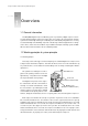
Design & installation Guide For McQuay MDS Multi System C H A P T E R 1 Overview 1.1 General information The MDS(Multi Digital Scroll) air conditioning system is operated by a digital compressor and is accommodated by multiple evaporators (indoor units). It is touted as the next-generation modular system in the world of high-efficiency air conditioning. lt has undoubtedly changed the face of cooling associated with high-storied buildings.
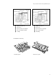
Design & installation Guide For McQuay MDS Multi System ■ PWM valve power off ■ PWM valve power on ■ Valve close ■ Valve open ■ Fixed scroll move downwards ■ Fixed scroll moves upwards ■ Two scrolls gather together ■ Two scrolls separate ■ Loading ■ Unloading 1.2.
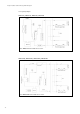
Design & installation Guide For McQuay MDS Multi System 1.2.3 System principle MDS030A、MDS040A、MDS050A、MDS060A Note: MDS030A unit excludes the reservoir. MDS030AR、MDS040AR、MDS050AR、MDS060AR Note: MDS030AR unit excludes the reservoir.
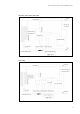
Design & installation Guide For McQuay MDS Multi System MDS080R、MDS100BR、MDS120BR MDS150BR -7-
Design & installation Guide For McQuay MDS Multi System MDS180BR MDS200BR、MDS220BR、MDS240BR -8-
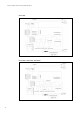
Design & installation Guide For McQuay MDS Multi System MDS260BR MDS280BR、MDS300BR -9-
Design & installation Guide For McQuay MDS Multi System 1.3 Main features 1.3.1 Wide range and stepless capacity modulation ■ Wide capacity modulation range(10%-100%) ; ■ According to changing the ratio of “loading time”and “unloading time, MDS can modulate the capacity steplessly; ■ Lower the energy consumption and running cost. 1.3.2 Accurate temperature control and quick response.
Design & installation Guide For McQuay MDS Multi System 1.3.4 Energy saving ■ The inverter system ’s capacity modulation range is from 30% to 100%, while MDS system ’s ■ ■ ■ ■ capacity modulation range is from 10% to 100%; Quick response to the capacity modulation; Min. power consumption is only 10% of the full load power consumption; Compared to t he inverter system, there is no power consumption of transducer; Compared to the nominal capacity scroll system, it can save 20% energy consumption. 1.3.
Design & installation Guide For McQuay MDS Multi System 1.3.7 Space saving ■ Compared to large size central air conditioning, MDS system is high centralized, no need for special equipment room to save more space, and bring more benefits. Traditional central air conditioning MDS system 1.3.
Design & installation Guide For McQuay MDS Multi System ■ Indoor unit: Ceiling exposed/floor standing unit M CM 050 T - A M A Design serial No. Matching outdoor units: MDS series Power supply features: A:220V~/50Hz Design serial No Cooling capacity No. Indoor unit: Ceiling exposed/floor standing unit McQuay ■ Indoor unit: ceiling concealed unit MCC 050 T R (B)/(D) - -A M A McQuay Concealed exposed indoor unit Cooling capacity No. Design serial No. Design serial No.
Design & installation Guide For McQuay MDS Multi System ■ Air-cooled cooling duct indoor unit M DB 050 T - A M A Design serial No. Matching outdoor units:MDS series Power supply features: A:220V~/50Hz Design serial No Cooling capacity No.
Design & installation Guide For McQuay MDS Multi System 1.5.2 Indoor products Model Capacity range 2.0HP 2.5HP 3.0HP 0.8HP 1.0HP 1.5HP 1.8HP ● ● ● ● ● ● ● ● ● ● ● MCC MCK ● MCM 4.0HP 5.0HP 6.0HP ● ● ● ● ● ● ● ● ● ● MDB ● 1.6 Performance Parameter 1.6.
Design & installation Guide For McQuay MDS Multi System 1.6.
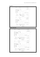
Design & installation Guide For McQuay MDS Multi System 1.6.5 Specification Model Unit Nominal cooling capacity kW MDS030A MDS030AR MDS040A 8.5 8.5 10 MDS040AR MDS050A 10 12.5 12.5 14.5 14.5 Nominal heating capacity kW - 9.0 - 11.5 - 13.5 - 16.5 Dimension Lx W x H mm 840x408x900 Weight kg 82 Cooling rated power input kW 3.0 3.0 A 13.6 13.6 kW - 2.5 A - 11.
Design & installation Guide For McQuay MDS Multi System 1.6.6 Specification Model MDS080B MDS080BR MDS100B MDS100BR MDS120B MDS120BR MDS150B MDS150BR MDS180B MDS180BR MDS200B MDS200BR Nominal cooling capacity kW 24.5 24.5 28.0 28.0 32.5 32.5 40.0 40.0 47.5 47.5 50.0 50.0 Nominal heating capacity kW - 26.0 - 30.0 - 34.0 - 43.0 - 50.0 - 53.
Design & installation Guide For McQuay MDS Multi System 1.7 Operating Range 【Note】The t able is gotten based on the equivalent length of 16m and the height is 0 m. 1.8 Refnet 1.8.1“Y”type unit:mm Length(mm) Refnet model A B C Diameter(mm) D E(outer diamenter F G Diameter(mm) H I(outer diamenter J K L Diameter(mm) M N(outer diamenter O P Q R MDS-Y1 553 172 293 120 28.6 28.9 25.7 22.5 28.6 28.9 25.7 22.5 19.3 22.2 19.3 16.1 12.9 9.7 MDS-Y2 420 142 223 80 15.88 16.1 12.9 9.
Design & installation Guide For McQuay MDS Multi System Type: MDS-Y5 unit: mm 1.8.
Design & installation Guide For McQuay MDS Multi System unit: mm 1.9 Outline of Indoor Units 1.9.
Design & installation Guide For McQuay MDS Multi System 1.9.2 MDB050T unit: mm 1.9.
Design & installation Guide For McQuay MDS Multi System 1.9.
Design & installation Guide For McQuay MDS Multi System 1.9.6 Auxiliary heating coil unit: mm Model A B C D HWT08-15 762 704 732 818 HWT18-30 1022 964 992 1078 HWT40-50 1372 1314 1342 1438 HWT60 1632 1574 1602 1688 1.9.7 Auxiliary electric heating box unit: mm Model -24- A B C D HDP1.2T08-15/HDP2.4T08-15 762 704 732 844 HDP2.4T18-30/HDP3.6T18-30 1022 964 992 1104 HDP2.4T40/HDP3.6T40/HDP4.8T40-50/HDP7.2T40-50 1372 1314 1342 1454 HDP5.4T60/HDP7.2T60/HDP10.
Design & installation Guide For McQuay MDS Multi System 1.10 Outline of Outdoor Units 1.10.1 MDS030A(R) unit: mm 1.10.
Design & installation Guide For McQuay MDS Multi System 1.10.3 MDS060A(R) unit: mm 1.10.
Design & installation Guide For McQuay MDS Multi System 1.10.5 MDS150B(R) unit: mm 1.10.
Design & installation Guide For McQuay MDS Multi System 1.10.7 MDS260B(R) unit: mm 1.10.
Design & installation Guide For McQuay MDS Multi System C H A P T E R 2 Units Control 2.1 Introduction of Controller MDS system is controlled by the micro-computer. Several types of controller are available, including wireless controller, wire controller, wire controller +remote controller and central controller. One wireless controller can control one unit, one wire controller can control one unit or up to 48 units, while central controller can control up to 512 units (32groups). 2.
Design & installation Guide For McQuay MDS Multi System 2.3 Operation of the Controller 2.3.1 Main features Both wire controller (using the key on board) and remote controller (equipped with infrared receiver to receive the order from the remote controller ) to control the unit, and to perform such functions as parameter setting , working mode setting, status display and malfunction indicating.
Design & installation Guide For McQuay MDS Multi System ● Temp unit setting There is a switch on the PCB board. When switch OP1 is ON, the unit is ℃; when it is OFF, the unit is Alternate method is as follows: Press“fan”key and last for 5 seconds in the normal condition, the temp unit setting will be successful and there will be a buzzer to indicate.
Design & installation Guide For McQuay MDS Multi System ● Timer setting Press “Timer ” to enter timer setting (When the unit is ON, it can only be set to OFF; When the unit is OFF, it can only be set to ON) and last timer will be shown on the LCD. If there is no press on any key within 5 seconds, it will exit and cancel the timer setting at the same time.
Design & installation Guide For McQuay MDS Multi System 2.3.3 Wire control panel For three-speed unit with wind wing For the cooling and heat pump unit with three-speed For the cooling and heat pump unit with single-speed For three speed unit with auxiliary heater For single speed unit with auxiliary heater 2.3.4 Outline dimension Unit:mm 2.3.
2.4.1 Real-time monitor software Design & installation Guide For McQuay MDS Multi System 2.4 Software Management System 2.4.1 Real-time monitor software ■ System monitor software: The real time monitor software of MDS unit can perform such functions as indoor monitor, system monitor and service monitor, for the purpose of making the user or service test personnel see the detailed parameters and know the operation of the unit.
Design & installation Guide For McQuay MDS Multi System ■ Loop monitor* Select and see the outdoor unit system figure, operation parameters and operation parameters of all indoor ■ Service monitor* Display the current operation parameters and history record curve of indoor outdoor unit inthe system. Note: the interface can be used by the authorized maintenance personnel. 2.4.2 User-specific biller ■ Based on real-time monitoring, McQuay has created user-specific billing software.
Design & installation Guide For McQuay MDS Multi System 2.5 Network Central Control ■ One outdoor unit can control up to 48 indoor units, and the central controller can control up to 32 outdoor units. The monitor software can perform the real time control up to 1536 (32*48) units at the same time. The connection cables for outdoor and indoor units are very simple. MDS system is equipped with strong alarm display and inquiry function to save the time and cost of maintenance.
Design & installation Guide For McQuay MDS Multi System 2.6 Wiring Diagram 2.6.
Design & installation Guide For McQuay MDS Multi System ■ Model MCK025/030/040/050T ■ MCM020/030T -38-
Design & installation Guide For McQuay MDS Multi System ■ Model MCM050T ■ Model MDB050/060T -39-
Design & installation Guide For McQuay MDS Multi System 2.6.
Design & installation Guide For McQuay MDS Multi System ■ Model MDS040A ■ Model MDS040AR -41-
Design & installation Guide For McQuay MDS Multi System ■ Model MDS050A ■ Model MDS050AR -42-
Design & installation Guide For McQuay MDS Multi System ■ Model MDS050AR ■ Model MDS060A -43-
Design & installation Guide For McQuay MDS Multi System ■ Model MDS060AR ■ Model MDS060AR -44-
Design & installation Guide For McQuay MDS Multi System ■ Model MDS080/100/120B ■ Model MDS080/100/120BR -45-
Design & installation Guide For McQuay MDS Multi System ■ Model MDS150B ■ Model MDS150BR -46-
Design & installation Guide For McQuay MDS Multi System ■ Model MDS180B ■ Model MDS180BR -47-
Design & installation Guide For McQuay MDS Multi System ■ Model MDS200/220/240B ■ MDS200/220/240BR -48-
Design & installation Guide For McQuay MDS Multi System ■ Model MDS260BR ■ Model MDS260/280/300BR -49-
Design & installation Guide For McQuay MDS Multi System ■ Model MDS280/300BR -50-
Design & installation Guide For McQuay MDS Multi System 2.7 Wiring Diagram 2.7.1 MDS030A/AR、MDS040A/AR、MDS050A/AR 2.7.
Design & installation Guide For McQuay MDS Multi System 2.7.3 MDS080~240B/BR 2.7.
Design & installation Guide For McQuay MDS Multi System 2.8 Electrical Date 2.8.1 Outdoor unit(MDS) Model MDS030A/MDS030AR MDS040A/MDS040AR Power supply Power Cross section area(mm2) Q.T.Y MDS050A/MDS050AR MDS060A/MDS060AR 220V~/50Hz 6(2.5) 2(1) Model MDS050A/MDS050AR MDS060A/MDS060AR Power supply Power Cross section area(mm2) cable Q.T.Y 380V /3N~/50Hz 4(2.5) 4(1) MDS080B/ MDS080BR Model MDS100B/ MDS100BR Power supply Power Cross section area(mm2) cable Q.T.
Design & installation Guide For McQuay MDS Multi System C H A P T E R 3 Selection 3.1 Load Calculation 3.1.1 Planning and cooperation McQuay recommends you to estimate and plan the following information before engineering. ■ Based on the air conditional area function, calculate out the cooling/heating load (depending on the temperature,humidity, and ventilation).
Design & installation Guide For McQuay MDS Multi System ■ If we know the heat performance index qv[W/(m3 . ℃)] and outside volume V (m3), we can calculate the heating load as follows: Qtotal = aqvV( tn – tw) Where, a is the correction factor. For details, see the table. qv is the heat performance index of the building. It is the heating load when the difference between the indoor temperature and the outdoor temperature is 1℃. For details, see the table. V is the outside volume of the building.
Design & installation Guide For McQuay MDS Multi System 3.2 Indoor unit selection ■ The selection of indoor unit should be based on the several factors, including customer ’s requirement, indoor air distribution, indoor decoration, etc. Ceiling concealed, ceiling cassette, high pressure duct unit and ceiling exposed are available now. ■ The indoor unit should be selected to meet the actual indoor load demand. The nominal cooling capacity should be is more than or equal to the actual indoor load demand.
Design & installation Guide For McQuay MDS Multi System 3.3 Selection of Outdoor Units For the combinations allowed, please refer to the "Indoor unit total capacity indexes ” table. The standard combination is the one with which the total indoor unit capacity is most proximate to but less than 100% of the capacity of the outdoor unit combination. 3.3.
Design & installation Guide For McQuay MDS Multi System 3.3.6 Actual capacity calculation ■ Based on the model and combination rate of the outdoor unit, select an appropriate door unit capacity table. Then find out the capacity of the outdoor unit (kW) and that of each indoor unit (kW) according to the rated temperatures of the indoor and outdoor units. The formula is as follows: IUC=OUC x (INX/T NX) Where, IUC is the actual capacity of each indoor unit. OUC is the capacity of the outdoor unit.
Design & installation Guide For McQuay MDS Multi System 3.3.9 Temperature-related cooling capacity correction factors 3.3.
Design & installation Guide For McQuay MDS Multi System 3.4 Design of Air System The air cooled pipeline unit is an important and complex part of the air system. The air system must be designed in compliance with Design Code for Heating, Ventilation and Air Conditioning and Code of Design on Building Fire Protection.
Design & installation Guide For McQuay MDS Multi System The conflux of the return air inlet brings little affect on the air flow pattern in the room. So, its structure is simple. Some only have a metal mesh in the orifice, or a shutter or grille. ● The return air inlet location and shape depend on the air flow pattern. If it is installed in the lower area of the room, the lower edge of the inlet must be at least 0.15 m away from the ground.
Design & installation Guide For McQuay MDS Multi System ● Check the air speed according to the actual pipe diameter, and calculate the actual speed, which should not larger than the recommended value in the design manual. ● Select the loop of most resistance and that of minimum resistance, and then calculate the frictional resistance and local resistance loss of each pipe segment. ● Check the unbalance ratio of the loop of most resistance to that of minimum resistance must be less than 15%.
Design & installation Guide For McQuay MDS Multi System ■ Wall thickness of the air pipe The wall thickness directly relates to the effect and life of the pipe. A too thin wall will cause unstable installation, and thus the pipe will sway within a large range to increase the noise. Even worse, the friction might compound the problem, shortening the service life of the air pipe or even the entire air conditioning system.
Design & installation Guide For McQuay MDS Multi System Acceptable (CO2) density Room type Acceptable CO2 density L/m3 g/kg Place where people stay for a long time 1 1.5 Place where children and patients stay 0.7 1.0 Place where people stay regularly (governmentagency) 1.25 1.75 2 3.0 Place where people stay for a short time In actual practice, the fresh air volume is generally 30 m2/h person or more, no matter how much room space a person occupies.
Design & installation Guide For McQuay MDS Multi System 3.5 Refnet joint selection 3.5.1 Copper pipe selection ( MDS100BR ) ■ Diameter of the main pipe and that of the remotest pipe(equivalent length<90m) Main pipe:φ 12.7/ φ 28.6(the same as the outdoor unit) The remotest pipe: the same as the indoor unit ■ Refer to the refrigerant pipe to calculate the cooling capacity of downstream A A-B-C: 17.4 KW A-D-E: 11.8 KW ■ Select the pipe diameter of downstream A Diameter of A-B: φ 12.7/ φ 25.
Design & installation Guide For McQuay MDS Multi System The following tables show the refrigerant copper pipe dimension specifications. For MDS-A series Outdoor unit capacit 3.0HP Specification 4.0HP/5.0HP 6.0HP Between the outdoor unit and the first tap joint Liquid pipe φ 9.52mmxt0.8 φ 9.52mmxt0.8 φ 9.52mmxt0.8 Gas pipe φ 15.88mmxt1.2 φ 19.05mmxt1.2 φ 19.05mmxt1.2 Between the tap joints Liquid pipe Gas pipe Total capacity of the indoor unit to which the pipe is connected.
Design & installation Guide For McQuay MDS Multi System Refnet joint type selection Y type Unit: mm Refnet joint type Length (mm) A B C Diameter (mm) D E(outer diameter) F G Diameter (mm) I(outer H diameter) J K L Diameter (mm) M N(outer diameter) O P Q MDS-Y1 553 172 293 120 28.6 28.9 25.7 22.5 28.6 28.9 25.7 22.5 19.3 22.2 19.3 16.1 12.9 MDS-Y2 420 142 223 80 15.88 16.1 12.9 9.7 12.7 12.9 9.7 6.5 12.7 12.9 9.7 MDS-Y3 420 142 223 80 15.88 16.1 12.9 9.7 12.7 12.
Design & installation Guide For McQuay MDS Multi System Type : MDS-C1 Unit: mm Type:MDS-C2、MDS-C3 Unit: mm -68-
Design & installation Guide For McQuay MDS Multi System C H A P T E R 4 Installation 4.1 Indoor unit installation 4.1.1 Ceiling cassette Do not install the indoor unit in a location where it will come into contact with the following elements: uneven circled air, saline gas, sulphide gas, machine oil, moist air and the place which can't support the weight of the unit. ■ Investigation before installation ● All field wiring must be installed in accordance with the local wiring regulation.
Design & installation Guide For McQuay MDS Multi System ● ● ● ● Make sure the distance between two Suspenders is 620.4mmX790.0mm; Use nut, Plat gasket and spring gasket to hang the unit though the suspender; Adjust the distance between the bottom surface of unit and ceiling to be 35.
Design & installation Guide For McQuay MDS Multi System ● Connecting the hose to the drainage pipe of outdoor unit; ● Pour the water through the water inlet port and check if there is any water leakage; ● When the test is finished, connect the other side of the hose to the drainage pipe of the indoor unit. ● The unit must be installed horizontally in order to prevent the water leakage and condensated water from generating.
Design & installation Guide For McQuay MDS Multi System ■ Grille installation ● Put the air filter into the its frame before install the grille first, ● Then put grille to the front panel; ● Please note that the white side of the air filter should face its frame; ● When decide the front grille installation direction, please consider if it easy to open the front grille. ● After the air filter has been used for 6 months or the color has turned to yellow, the air filter is invalid.
Design & installation Guide For McQuay MDS Multi System ● Some units need an electronic expansion valve box (throttle box) for condensate pipe installation, as shown in the right figure: Note: The electronic expansion valve box of the indoor unit must be placed in the throttle box and installed in an appropriate position of the liquid pipe.
Design & installation Guide For McQuay MDS Multi System 4.1.3 High static pressure duct unit ■ In order to keep the unit runs in a good condition, the air inlet port should be at least 3m. ■ Soft connecting joint should be used to reduce the sound level and the vibration. ■ Condensated water pipe should have a slope with no less than 0.5%~1%, and it must be insulated. ■ Condensate water pipe should have a trap.
Design & installation Guide For McQuay MDS Multi System ■ Make sure supports and hangers are provided to the horizontal and vertical air pipes, and stowwood is added between the support or hanger of the insulation air pipe and the insulation layer. For the distance between the support and hanger, refer the following table: Larger side of the rectangle air pipe (mm) Distance between the support and the hanger (mm) ≤ 500 630-1000 ≥ 1250 <3 < 2.
Design & installation Guide For McQuay MDS Multi System 4.2 Outdoor unit installation 4.2.1 Lifting to mount the outdoor unit Please lift to mount the unit as shown below. When moving the outdoor unit, you should support it on four points, instead of 3 support points. If only 3 support points, the unit may be unstable, and even fall off. Notes: Make sure to move the outdoor unit carefully. If there is package belt with the product, this belt can not be used to lift or move the product.
Design & installation Guide For McQuay MDS Multi System ■ MDS030~060A/AR Units Min.
Design & installation Guide For McQuay MDS Multi System 4.2.2 Parallel Unit Installation (For MDS260/280/300) The parallel unit means to connect two outdoor units as an integrated unit to connect the indoor unit. The installation of the parallel unit is more complex than that of a single unit. Please read this manual carefully before installation, and install according to the instructions. ■ Outdoor unit installation location The parallel unit is divided into master unit and slave unit.
Design & installation Guide For McQuay MDS Multi System ■ Connection of the system balance pipe ● Make sure the system balance pipe is connected. The system balance pipe should be connected to the unit through the continuous side hole in the chassis or that in the side panel or that in the unit piping position. ● The balance pipe must be connected orderly, and the connection higher than the level of the pipe to stop valve of the balance pipe.
Design & installation Guide For McQuay MDS Multi System 4.3 Refrigerant piping design and installation 4.3.1 Refrigerant piping design ( including selection of refnet joint ) ■ Capacity combination The indoor units & outdoor units should have a relationship as follows: ∑ indoor units' cap 50% ≤ ∑ outdoor units' cap ≤ 130% Note:We strongly recommend that the capacity modulation equals to 100%. ■ Refrigerant piping limit Allowable value Actual length Piping Max.
Design & installation Guide For McQuay MDS Multi System ■ Equivalent length ● Equivalent length = actual pipe length + number of elbows X equivalent length of each elbow + number of oil traps X equivalent length of each oil trap. Item Diameter elbow(m) oil trap(m) 9.52 0.18 1.3 12.70 0.20 1.5 15.88 0.25 2.0 19.02 0.35 2.4 22.02 0.40 3.0 25.40 0.45 3.4 28.58 0.50 3.7 31.80 0.55 4.0 ● For example: when 10HP outdoor unit's actual length is 80m, the piping diameter is 25.
Design & installation Guide For McQuay MDS Multi System ■ Connection of refnet joint and distributor kit Only connected by the refnet joint Only connected by the distributor kit Connected by the refnet joint and the distributor kit -82-
Design & installation Guide For McQuay MDS Multi System ■ Refrigerant piping installation: ● Refrigerant piping should use the appointed diameter pipe; ● Refnet joint must be installed horizontally or vertically. ● Distributor kit must be installed horizontally. ● Distributor kit should be connected to indoor unit directly, it is not allowed to connected to the distributor kit or refnet joint.
Design & installation Guide For McQuay MDS Multi System ● The Exv must be installed vertically 4.3.
Design & installation Guide For McQuay MDS Multi System 4.3.3 exchange way of Nitrogen gas (when welding copper tube) Suppose no nitrogen gas is injected into refrigerant pipe when welding, the oxide air bubble will come into being in the internal surface of tube. This will result in some damage to the system. In order to avoid these, nitrogen gas should be injected into refrigerant pipe when welding, this process is called nitrogen gas exchange method. This is the standard operation process of welding.
Design & installation Guide For McQuay MDS Multi System 4.3.4 Transportation and conservation of copper tube ■ When transport the connecting pipe, please be careful to keep it in shape. Copper cap should be used to prevent the dirt and water from entering it. When store it, the side of the connecting pipe should be sealed as follows: ■ Be careful when there are some operation as follows: ● Put the copper pipe through a hole ( The dirt is easy to enter it).
Design & installation Guide For McQuay MDS Multi System ■ Steps: ● Put the pressure adjustor on the nitrogen bottle ● Connect the pressure adjustor with the liquid pipe of the outdoor unit ● Seal any other connecting port, ● Open the valve of the nitrogen and adjust it which the pressure value is 5kg/cm2. ● Check to see if the nitrogen go through the liquid pipe of point A. ● Air blow ◆ Hold a insulation material in your hand and try to seal the side of the copper pipe.
Design & installation Guide For McQuay MDS Multi System 4.3.7 Process sequence of air leakage test refrigerant piping assembly finished Pressure charging No is the pressure released? Pass yes check and maintain it ■ Main points of testing Please test as follows: ● The Pressure charging must be tested both in liquid pipe and gas pipe. ◆ First step, keep 3.0kg/cm2 pressure gas for more than 3 minutes---may be can find big gap; ◆ Second step, keep 15.
Design & installation Guide For McQuay MDS Multi System 4.3.8 Air leak gap checking ■ Test 1 (when the pressure reduces) ● Hearing — use your ear to find it out. ● Touching — use your hand to find it out. ● Soap water — use soap water to find it out. ■ Test 2 (when step 1 can not find out , then the following should be adopted) ● Reduce nitrogen pressure to 3.0kg/cm2; ● Charge the nitrogen with R22 to 5.
Design & installation Guide For McQuay MDS Multi System ■ Key points The thickness of insulation materials depends on the pipe size. Pipe size Thickness of the insulation material 6.4mm~25.4mm 10mm or more 28.6mm~38.1mm 15mm or more ● In case the environment is hot and damp, increase the recommended thickness (1 inch for the main pipe, and half inch for the refnet joint) in the table above.
Design & installation Guide For McQuay MDS Multi System A Valve handle (Before pipe connection, vacuum pumping and additional refrigerant filling for delivery, make sure this valve is closed completely. After the above operations, please fully open it.) B Stop pin (prevent the valve handle from turning over 90 degrees) C Sealing plate (annex) D Connection pipe (annex) Install the pipe firmly to the valve flange with the sealing plate to avoid gas leakage.
Design & installation Guide For McQuay MDS Multi System 4.3.11 Refrigerant filling Calculate the refrigerant amount according to the length of the liquid pipe Add additional refrigerant ■ The refrigerant amount of fill of the outdoor unit before delivery (excluding the refrigerant to be filled in the site pipe) ■ The additional amount of the refrigerant depends on the liquid pipe diameter and length (based on the liquid pipe). Diameter of the liquid pipe (mm) 6.35 9.52 12.7 15.88 19.
Design & installation Guide For McQuay MDS Multi System ● Selection of vacuum pump When selecting a vacuum pump, please pay attention to the follows: ◆ The range of vacuum pump must be up to -755mmHg ◆ The vacuum pump should have a large air flow (more than 40 litres/min). Water boiling point(c) pressure(mmHg) vacuity(mmHg) 40 55 -705 30 36 -724 26.7 25 -735 24.4 23 -737 22.2 20 -740 20.6 18 -742 17.8 15 -745 15.0 13 -747 11.7 10 -750 7.
Design & installation Guide For McQuay MDS Multi System Type of vacuum pump and the vacuity Application Type Max. air flow vacuum drying air discharge Suitable Suitable unsuitable Suitable unsuitable Suitable 0.02mmHg vacuum pump with lubricant 100L/min 10mmHg vacuum pump without lubricant 40L/min 0.
Design & installation Guide For McQuay MDS Multi System ■ Special vacuum drying This vacuum drying way is used when there are some moisture in the copper pipe. Operating sequence: 1. Vacuum drying: pumping the system for 2 hours; 2. Nitrogen charging: Charge the nitrogen to the pressure of 0.5kg/cm2; As Nitrogen is a dried gas, so it can dry the system; but if the moisture is too much, maybe it can not dry the system thoroughly.
Design & installation Guide For McQuay MDS Multi System 4.4 Design, processing and installation of condensated drain pipe 4.4.
Design & installation Guide For McQuay MDS Multi System 4.4.2 Making and mounting accessory condensate pipes Procedure: Install the indoor units check for water leakage connect the condensate pipe insulate the pipe from heat 4.4.3 Slope and supporter of condensate pipe ■ The slope condensate pipe should be more than 1/100 ● The length of condensate pipe should be as short as possible to discharge the condensate water (no air pocket on the way).
Design & installation Guide For McQuay MDS Multi System 4.4.5 The main drainage pipe of multiple indoor units ■ The pipe should be mounted from the upstream, and the diameter of the downstream connecting pipe should be as long as possible. ■ The pipe should be as short as possible and the number of the indoor units must be as small as possible. 4.4.6 Accessory condensate pipe (hose) If the condensate collector is made of polystyrene, it should use the hose.
Design & installation Guide For McQuay MDS Multi System 4.4.8 Installation of the drainage lift pipe Use the gradienter to check if the indoor unit is parallel to the ceiling, If the drainage pipe needs to be lifted up, it should be less than 300mm. If it is more than 500mm, maybe it will result in the refrigerant leakage. After connecting, the hose should not be higher than the connecting port. This can prevent the water from flowing backwards.
Design & installation Guide For McQuay MDS Multi System C H A P T E R 5 Testing 5.1. MDS hardware diagram and configuration 5.1.1 MDS series indoor units 3-speed fan Power supply Electronic expansion valve Temperature measurement Communication port 1 indicator Communication port 2 Electric heater Swing Memory 3 The indoor unit consists of a three-speed fan and an electronic expansion valve (electric heater and swing function optional).
Design & installation Guide For McQuay MDS Multi System Address settings (SW2.1___SW2.6) Unit address SW2.1 SW2.2 SW2.3 SW2.4 SW2.5 SW2.
Design & installation Guide For McQuay MDS Multi System Model 1 setting(SW3.5 —— SW3.8) Model 2 SW3.5 SW3.6 SW3.7 SW3.8 MCC 0 0 0 0 MCK 0 0 0 1 MCM 0 0 1 0 MWM 0 0 1 1 MDB 0 1 0 0 MDBX 0 1 0 1 Reserve Power setting(SW3.1 —— SW3.4) Power SW3.1 SW3.2 SW3.3 SW3.4 0.8HP 0 0 0 0 1.0HP 0 0 0 1 1.5HP 0 0 1 0 1.8HP 0 0 1 1 2.0HP 0 1 0 0 2.5HP 0 1 0 1 3.0HP 0 1 1 0 4.0HP 0 1 1 1 5.0HP 1 0 0 0 6.0HP 1 0 0 1 7.
Design & installation Guide For McQuay MDS Multi System Description of controller hardware ■ Input port: The system contains 5 test ports designed for high/low pressure test, digital compressor overload, constant speed compressor overload 1 and constant speed compressor overload 2 (used when 3 compressors are available) ■ Output port: The system contains 9 output control ports including PWM valve, 4-way valve, digital compressor/constant-speed compressor main power supply, high/medium/low wind, SI (reserve
Design & installation Guide For McQuay MDS Multi System J2 settings (1: ON: 0: OFF) D1~D5 indicate the local address during intercommunication: J2.1 J2.2 J2.3 J2.4 J2.5 Address J2.1 J2.2 J2.3 J2.4 J2.
Design & installation Guide For McQuay MDS Multi System DIP switch setting Note: 1: 1: ON, 0: OFF S1 (1~2) 1 2 1 MDS~A Cooling only 0 MDS~B Heat pump S1 3~8 indicate the number of connected indoor units Qty 3 4 5 6 7 8 Qty 3 4 5 6 7 8 1 0 0 0 0 0 0 25 0 1 1 0 0 0 2 0 0 0 0 0 1 26 0 1 1 0 0 1 3 0 0 0 0 1 0 27 0 1 1 0 1 0 4 0 0 0 0 1 1 28 0 1 1 0 1 1 5 0 0 0 1 0 0 29 0 1 1 1 0 0 6 0 0 0 1 0 1 30 0 1 1 1 0
Design & installation Guide For McQuay MDS Multi System S2 (4~8) addresses of the outdoor unit Address No. 4 5 6 7 8 Address No.
Design & installation Guide For McQuay MDS Multi System 5.2 Trial Run ■ Precautions ● Power up the system 12 hours while you run it for the first time so that the shaft can be preheated in advance; ● After the main power supply is switched off, please don ’t start the second trial run until the system is powered for 2.5 hours; ● If the heater is not heated, to protect the compressor, don't start the system until it is powered for 2 hours.
Design & installation Guide For McQuay MDS Multi System C H A P T E R 6 Servicing and Maintenance 6.1 User Guide 6.1.1 Responsibilities and obligations This product is covered under MacQuay ’s warranty during the warranty period. Only MacQuay’s technicians or experienced professionals designated by MacQuay are allowed to install, test, repair and maintain this product series. 6.1.2 Unpacking inspection Upon receipt of the units, please check them against the packing list.
Design & installation Guide For McQuay MDS Multi System 6.2 Servicing and Maintenance ! Caution: ■ Do not use or place inflammable and explosive articles beside the air-conditioning unit; ■ Power the indoor units in a centralized way; ■ Please check the parts like installing support often to see if they are damaged after longtime service; ■ Do not alter or repair the product without authorization.
Design & installation Guide For McQuay MDS Multi System ● Fan motor This component requires only a little care. As the motor is lubricated and sealed before the equipment leaves factory, no more lubrication is needed. After the unit remains in service for six months, be sure to check the fan motor is entirely insulated from the ground. ● Heat exchanger Clean the dust and foreign matters from the surface of heat exchanger using a cleaner together with a nylon brush.
Design & installation Guide For McQuay MDS Multi System ■ Maintenance and care of indoor unit MCK Although the air-conditioner is designed to have a long service life even with minimal care, be sure to check it at regular intervals throughout its service, so that you can use the air-conditioner better. Part Air filter (indoor unit) Indoor unit Condensate water collector and pipe Indoor fan Indoor fan, coil pipe of outdoor unit Procedure Recommended interval 1.
● Care of the heat exchanger Maintain the heat exchanger once around the end of the running season. If a blade of the heat exchange falls sideways, be sure to put it upright. If any dust or foreign matter is present on the surface of the heat exchanger, use a clean together with a nylon brush to clean it. If compressed air source is available, please use it to blow away the dust from the surface of the heat exchanger.
C H A P T E R 7 Fault Codes and Troubleshooting 7.1 Fault codes here refer to the codes that appear on the remote control. If a host computer is available, the fault cause is directly displayed. 7.1.1 Fault codes for MDS-A/B series No. Fault code Description No. Fault code Description 1 E0 System malfunction 34 H5 Sensor broken, high pressure 2 E1 Sensor broken(TH1 discharge temp) 35 H6 Discharge temp.
Indication Light Twinkle Related to Malfunction Code: Heat Fan Dry Coo Sensor, outdoor Type F F F F Sensor, indoor F F F ON System failure F F F OFF Heat Fan Dry Coo Pump, indoor F F ON F Over load, compressor F F ON ON Pressure sensor,outdoor F F ON OFF Heat Fan Dry Coo Pressure high/low F F OFF OFF Communication F OFF F F Others F OFF F ON Type Type ● The following phenomena are not unit malfunctions: Some odorous gas blows from the unit, because
C H A P T E R Annexes Annex 1 Outdoor weather parameters of major Chinese cities City Annual average temperature℃ Outdoor temperature℃ Summer Winter Designed indoor temperature Beijing 11.4 30~36 -12~-5 22~25 Shanghai 15.7 31~40 -4~ 3 22~25 Guangzhou 21.8 33~38 3~12 22~25 Tianjin 12.2 29~36 -11~-4 22~25 Shijiazhuang 12.9 32~38 -11~-3 22~25 Shenyang 7.8 28~33 -22~-12 22~25 Jinan 14.2 29~36 0~-5 22~25 Qingdao 12.2 27~32 -1~-6 22~25 Lianyungang 14.
Annex 2 (1) Parameters designed for various kinds of buildings Cooling load (w/m2) Building Sensible cooling load Occupants Lighting Air flow Max. noise Total cooling load m2/person W/m2 L/S dB(A) Middle 65 95 10 60 5 35~50 Far side 110 160 10 60 6 35~55 Individual office 160 240 15 60 8 30~45 Meeting room 185 270 3 60 9 40~60 Classroom 130 190 2.5 40 9 35~40 Library 130 190 6 30 9 35~40 Cafeteria 150 260 1.
Annex 2 (2) Heat load indexes designed for air-conditioning in some of the Chinese buildings No. Building type and room name Heat load index W/m2 No. Building type and room name Heat load index W/m2 1 Office building,school 58-80 6 Store 64-87 2 Residential building 46-70 7 Single-floor residential building 85-105 3 Hospital, kindergarten 64-80 8 Dining room 4 Hotel 58-70 9 Cinema 5 Library 46-76 116-140 93-116 Annex 3 Max.
Annex 9 Confirmation Form 1. Use the Confirmation table to add more secondary refrigerant ■ Calculate the additional amount of secondary refrigerant required according to the diameter and length of the copper pipes. ■ The table below lists the formula used to calculate the additional amount of secondary refrigerant needed for liquid copper pipes of various diameters (The amount of secondary refrigerant required for the pipes that come with the indoor unit is already available).
4. Table of codes for connected indoor Address Indoor unit model Location of the indoor unit Address Indoor unit model 0 24 1 25 2 26 3 27 4 28 5 29 6 30 7 31 8 32 9 33 10 34 11 35 12 36 13 37 14 38 15 39 16 40 17 41 18 42 19 43 20 44 21 45 22 46 23 47 Location of the indoor unit Total capacity of the indoor units (HP): 5.
WWW.MCQUAY.