
Installation guide


-96-
Design & installation Guide For McQuay MDS Multi System
4.4 Design, processing and installation of condensated drain pipe
4.4.1 Design of condensated piping
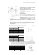
■ Size selection of main pipe and vertical pipe of condensated water
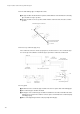
Choose the pipe size according to the condensated water flow from the main pipe of indoor
unit and the following table;
Suppose the condensated water flow of 1 HP is 2L/h, then the condensated water flow of 3#
2HP and 2# 3HP is calculated as follows:
2(L/h)x 2(HP) x 3(sets) +2L/h x 3(HP) x 2(sets) = 24L/h.
Note:
Suppose the moisture is 10% in the pipe.
After the header pipe, the pipe should be larger or equal to VP30.
Note:
The vertical pipe should be larger than VP30
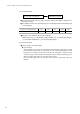
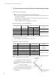
Vertical pipe Vs condensated water flow rate
JIS Polyethylene pipe diameter(mm) allowable flow rate(L/h) Remark
VP20 20 220
unsuitable for
VP25 25 410
theheader pipe
VP30 31 730
VP40 40 1,440
VP50 51 2,760
Suitable for the header pipe
VP65 67 5,710
VP75 77 8,280
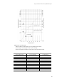
Main horizontal pipe Vs condensated water flow rate
JIS
Polyethylene pipe allowable flow rate(L/h)
Remark
diameter(mm) slope ≥ 1/50 slope ≥ 1/100
VP20 20 39 27 unsuitable for the
VP25 25 70 50 header pipe
VP32 31 125 88
VP40 40 247 175 Suitable for the header pipe
VP50 51 473 334
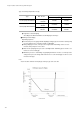
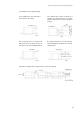
For example, The condensate pipe of one
2HP and two 4HP indoor units are connected to a
pipe as shown on the right, and its water drainage
capacity is:
4L/h + 8L/h × 2=20L/h
So the horizontal vertical pipe diameter shall
be 30 or more, and the diameter of the vertical
diameter shall not be less than that of the horizon-
tal vertical pipe.