Engineered for flexibility and performance.
Contents General Features ............................................................................................................. 2 Nomenclature................................................................................................................... 4 Technical Parameter ........................................................................................................ 7 Outlines and Dimensions .............................................................................................
1 General Features 1.1 Wide Range and Stepless Capacity Modulation • • Running ration of compressors % • Wide capacity modulation range (10%-100%) According to changing the ralio of “loading time” and “unloading time”. MDS can modulate the capacity steplessly. Lower the energy consumption and running cosl. MDS system Inverter system Total capacity of operating indoor units 1.2 Accurate Temperature Control and Quick Response • The cooling/heating capacity of the indoor units is controlled by the EXV.
1.4 Energy Saving The inverter system’s capacity modulation range is from 30% to 100%, while MDS system’s capacity modulation range is from 10% to 100%. Quick response to the capacity modulation. Min. power consumption is only 10% of the full load power consumption. Compared to the inverter system, there is no power consumption of transducer. Compared to the nominal capacity scroll system, it can save 20% energy consumption.
1.7 Space Saving • Compared to scale size central air conditioning, MDS system is high centralized, no need for special equipment room to save more space, and bring more benefits. Traditional central air conditioning MDS system 1.8 Easy to Install and Simple to Maintain Easy Installation • MDS system is simple and reliable, and outdoor unit can be connected with several indoor units, so it is easy for installation.
Nomenclature 2.1 Indoor Unit: Ceiling Cassette M CK 030 T -A M A Design alteration No Matching outdoor units: MDS series Power supply feature: 220V~/50Hz Design serial No. Cooling capacity No. Ceiling cassette indoor unit McQuay 2.
2.5 Electric Heater Box HD P 1.2 T 08-15 8-15 means it can be used in MCC008/010/015T 18-30 means it can be used in MCC018/020/025/030T 40 means it can be used in MCC040T 40-50 means it can be used in MCC040/050T 60 means it can be used in MCC060T Applicable units: T means the unit can be used in MCC "T" series Heating capacity (kW) Heating unit: P means the heating unit is PTC Omitted means the heating unit is electric heating pipe Electric heater box 2.
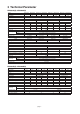
3 Technical Parameter MDS030A(R)~MDS060A(R) Model MDS030A MDS030AR MDS040A MDS040AR MDS050A MDS050AR MDS060A MDS060AR Cooling(kW) 8.5 8.5 10.0 10.0 12.5 12.5 14.5 14.5 Heating(kW) - 9.0 - 11.5 - 13.5 - 16.5 Power 220V~/50Hz Noise dB(A) 59 W×D×H(mm) 840×408×900 59 59 1058×430×1044 1058×430×1044 60 1058×430×1247 Weight(kg) 82 85 112 115 117 120 123 Power consumption in cooling(kW) 3.0 3.0 3.5 3.6 4.4 4.4 5.0 130 5.0 Ampere in cooling(A) 13.6 13.6 15.
MDS180B MDS180BR MDS200B MDS200BR MDS220B MDS220BR MDS240B MDS240BR Cooling(kW) Model 47.5 47.5 50.0 50.0 55.0 55.0 65.0 65.0 Heating(kW) - 50.0 - 53.0 - 58.0 - 68.0 380V/3N~/50Hz Power Noise dB(A) 66 66 W×D×H(mm) 66 68 1990×840×1840 Weight (kg) 520 550 560 590 560 590 570 600 Power consumption in cooling(kW) 14.1 14.1 15.2 15.2 16.7 16.7 19.8 19.8 Ampere in cooling (A) 28.2 28.2 31.1 31.1 32.7 32.7 38.5 38.
MCC025T MCC030T MCC040T MCC050T MCC060T Cooling capacity(W) Model 6500 7800 10600 12400 14400 Heating capacity(W) 7400 8900 11600 14500 17300 Power 220V~/50Hz Noise dB(A) 37 W×D×H(mm) 42 1290×490×250 47 48 1640×490×250 1900×490×250 Weight(kg) 27 28 39 45 Power input(W) 123 158 276 280 3 4 960 1200 1900 2100 15(0/30/50) 30(15/50/70) Fan number 2 Air flow(H : m³/h) ESP(Pa) DrainΦ(mm(in)) 50(15/30/70) 19.
Ceiling Cassette Indoor Unit MCK010T MCK015T MCK018T MCK020T MCK025T MCK030T MCK040T MCK050T Cooling capacity(W) Model 2800 3600 4500 5400 6500 7500 10000 12500 Heating capacity(W) 3200 3900 5000 5900 7200 8000 11000 13500 42 45 45 48 220V~/50Hz Power Noise dB(A) 29 32 W×D×H(mm) 38 39 930×930×278 930×930×363 Weight(kg) 26 26 30 30 39.5 39.5 39.5 39.
4 Outlines and Dimensions 4.
MDS040A(R)/MDS050A(R)/MDS060A(R) Unit: mm Model H1 H2 1024 1044 MDS050A(R) 1024 1044 MDS060A(R) 1222 1242 356 430 94 1006 430 816 356 94 115 390 94 115 390 MDS040A(R) 94 816 67 128 67 128 H2 H1 H2 H1 1006 page 12
MDS080,100,120,150,180,200,220,240,260,280,300B(R) Model A B MDS080/100/120B(R)/ 120B(R)M 900 990 Model Unit: mm A B MDS150B(R)/130B(R)S/ 150B(R)M/150B(R)S 1200 Model 1290 MDS180/200/220/ 240B(R) C D 950 1990 MDS260/280/300B(R)are combined units, made up by a master unit and a slave unit Combined unit MDS260B(R) MDS280B(R) MDS300B(R) Master unit + Slave unit MDS120B(R)M+MDS150B(R)S MDS150B(R)M+MDS130B(R)S MDS150B(R)M+MDS150B(R)S D 990+10+1290 1290+10+1290 1290+10+1290 Deta il 1
MCK010,015,018,020,025,030,040,050T Unit: mm Model A B C D E F G H I J K L M MCK010/015/018/020T 820 875 548 820 278 250 28 930 930 642 622 555 555 MCK025/030/040/050T 820 875 548 820 363 335 28 930 930 642 622 555 555 MDB050, 060T Unit: mm Model A B C D E F Gas pipe Liquid pipe MDB050T 995 957 998 1032 1063 1230 Φ19.05 Φ9. 52 MDB060T 1195 1157 1198 1232 1263 1430 Φ19.05 Φ9.
MCM020, 030, 050T Unit: mm Model A B C D E F G H J K L M N MCM020T 1174 75 1082 68 58 156 1214 57 670 216 319 879 517 MCM030T 1174 75 1082 68 93 156 1214 57 670 216 319 879 517 MCM050T 1674 75 1582 68 93 156 1714 57 670 216 319 1379 517 page 15
5 Wiring Diagram 5.
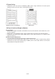
Model: MCK025/030/040/050T J1 SW-PB KEY1 JP7 J5 J4 HF LF LINE J2 B A J6 NEUTRAL JP2 JP1 JP6 JP3 red JP4 L blue N N N SW3 ON SW1 Connecting indoor/outdoor units communication ON DIP SW2 ON DIP 1 2 Water level switch SW-PUMP red blue black blue white blue yellow/green M ~ Transformer Remote R receiving Swing motor Indicator M ~ M ~ yellow/green Coil outlet temperature sensor EXV Electronic expansion valve Coil middle temperature sensor Indoor return air tempe
Model: MCM050T J1 SW-PB KEY1 JP7 HF MF LINE J3 N N LF MF HF ON 1 CON3 L yellow JP4 brown JP5 red NEUTRAL JP2 JP6 orange B A J5 2 3 SW1 ON DIP SW2 4 ON DIP 5 Connecting indoor/outdoor units communication 6 7 6 8 6 DIP 5 Coil outlet temperature sensor Coil inlet temperature sensor Coil middle temperature sensor yellow/green black black Transformer Remote receiving yellow/green Indoor return air temperature senso red blue yellow brown orange blue yellow
Model: MDS030A 220V~/50Hz N FU 2 PWMV KM 5 8 10 LOW-FAN 1L1 3L2 7 FIXED COMP DIG COMP 4WV PWMV 3 HI-FAN EXV MID-FAN N L KM LIVE 2T1 4T2 N RY1 RY2 RY3 RY5 RY4 RY6 RY7 NEUTRAL red white Transformer C2 M ~ 14 OV-COMP1 J1 Fan 1 Connecting indoor units communication Jumper settings: Symbol Description Symbol Description PTC Compressor start-up unit FU Fuse KM Contactor EXV Electric expansion valve C1-2 Capacitor PWMV Solenoid valve HP High pressure switch
Model: MDS040A 220V~/50Hz N N FU 2 PWMV KM 5 HI-FAN 8 10 LOW-FAN 1L1 3L2 5L3 7 FIXED COMP DIG COMP 4WV PWMV 3 MID-FAN L KM LIVE 2T1 4T2 6T3 N RY1 RY2 RY3 RY5 RY4 RY6 RY7 NEUTRAL red yellow brown orange blue yellow brown 14 red Fan 1 OV-COMP1 J1 Fan 2 JP1 GND DLT A B AI-IN Connecting indoor units communication Description of components and parts: Jumper settings: Symbol Description Symbol Description JP1 JP2 PTC Compressor start-up unit FU Fuse OFF O
Model: MDS050A 220V~/50Hz N FU 2 PWMV KM 5 8 10 MID-FAN LOW-FAN 1L1 3L2 5L3 7 HI-FAN DIG COMP 4WV PWMV 3 FIXED COMP L KM LIVE 2T1 4T2 6T3 N RY1 RY2 RY3 RY5 RY4 RY6 RY7 NEUTRAL brown yellow orange McQuay Transformer 13 white red 14 red Fa n 1 OV-COMP2 TRAN-L M ~ J1 Fan 2 JP1 GND DLT A B AI-IN Connecting indoor units communication Description of the components and parts: Jumper settings: Symbol Description Symbol Description PTC Compressor start-up unit
Model: MDS050AR 380V/3N~/50Hz N R S T 71 81 red green yellow DB3A L FU RC EXV 4WV 21 OL L1 LIVE N NEUTRAL RY1 RY2 23 LOW-FAN HI-FAN RY3 22 MID-FAN KM FIXED COMP DIG COMP 4WV PWMV 1 RY5 RY4 RY6 RY7 NEUTRAL yellow brown Transformer 18 Digital compressor red C2 20 Fan 1 red Fan 2 JP1 Description 4WV DLT GND AI-IN Symbol Description FU Fuse Electronic expansion valve OL JP1 JP2 12.
Model: MDS060AR 220V~/50Hz N N L FU 2 19 K3 18 K2 17 K1 RC K1 KM 8 10 MID-FAN HI-FAN DIG COMP 22 7 FIXED COMP 21 4WV PWMV 3L2 2T1 4T2 K3 K2 5 3 LOW-FAN EXV KM LIVE RY1 RY2 RY5 RY4 RY3 RY6 RY7 NEUTRAL N brown orange blue black Fa n 1 OV-COMP1 J1 Fan 2 JP1 GND DLT A B AI-IN Description of the components and parts: Symbol Description Symbol Description PTC Reverse phase-loss protector FU Fuse 4WV Electronic expansion valve LP 11 LP HP 12 HP J
Model: MDS080/100/120B LOW-I TR KM1 KM2 KM3 KM4 OL1 OL2 OL3 OL4 HI-1 TH7 TH5 TH3 LPT 1 2 3 red white hit bl k black blue TH12 TH11 LOW-U V2- 25 26 Apc Bin Ain 12 OL2 13 J1 L Digital compressor EXV1 Reversion Symbol Description FU Fuse KM Contactor Overcooling electronic expansion p valve HP High pressure switch Solenoid valve LPT Low pressure sensor TR Fan motor 10 2 4 KM3 KM4 3 5 OL Overload protection Transformer Model MDS080B OL4 0.67A MDS120B 1.
FU blue yellow LOW-I TR white T1 T2 M ~ T3 T1 T2 M ~ T3 yellow Bpc Apc Bin Ain 13 OL3 14 MDS-P 26 Constant-speed compressor 2 HP 15 OL4 16 OL5 17 HP M ~ J1 Digital compressor Connecting the indoor unit Connecting central control n system DIG-OL EXV1 L EXV4 J18 1 Constant-speed compressor 1 HI-U 30 FIX1 T3 OL1 FIX2-OL FANH T2 M ~ 12 FANL 24 OL2 LOW-U MDS-M V2- SV1 23 red 21 L1 T1 TH4 TH2 OL5 blue yellow red blue yellow red red OL4 TH7 TH6 TH5 T
Model: MDS180B FU Ambient temperature sensor TH8 R S L blue yellow 71 red Air discharge temperature sensor of the digital compressor TH1 380V/3N~/50Hz TR LOW-I HI-1 TH7 TH6 TH5 TH3 TH9 TH8 TH4 TH2 TH1 V1+ V1V2+ V2- KM4 KM3 MDS-E EXV2 KM2 MDS-M SV2 L FANL3 FANH3 FANH2 HP 15 T1 T2 M ~ T3 T2 T1 M ~ T3 T2 T1 M ~ T3 FIX2 DIG 4WV1 4WV2 PMW S2 EXV1 black brown M ~ 43 white white black 41 brown blue yellow red blue yellow red blue yellow red S1 36 37
Model: MDS200/220/240B blue TR LOW-I HI-1 TH7 TH5 TH3 Air discharge temperature sensor of the digital compressor TH1 Ambient temperature sensor TH8 Before overcooling circuit temperature sensor TH9 After overcooling circuit temperature sensor TH10 TH11 TH10 TH8 TH4 LPT HPT 3 red yellow red R S Overcooling circuit outlet temperature sensorTH11 Air suction temperature sensor TH12 380V/3N~/50Hz TH1 HI-U V1+ V1V2+ MDS-E MDS-M Bin Ain EXV2 V2- EXV3 L L SV2 L FANL3 FANH3 FANL2
LOW-I TR KM3 OL1 OL2 OL3 KM4 TH11 V1V2+ TH4 TH2 white 30 J1 Apc DIG EXV1 L 1 2 7 4 10 Digital compressor Fan motor EXV4 11 EXV1 KM3 Constant-speed compressor Connecting central n control system S3 FIX1 S2 FANH N FIX2 white black S1 HP M ~ Shaft heater heater 33 MDS-P FANL T3 17 HP Connecting the slave unit 32 DIG-OL SV1 M ~ FIX1-OL SV2 T1 T2 13 LP L1 T2 OL2 4WV 25 26 brown 24 12 PMW blue yellow red red 31 OL1 HI-U MDS-M V2- FIX2-OL 19
Model: MDS280/300BR (Master Unit) 380V/3N~/50Hz N T R FU T 71 LPT KM2 KM4 KM5 TH5 TH3 V1V2+ white a unit 31 Connecting the slave Digital compressor L Apc S3 DIG M ~ heater S2 4WV HP J1 Shaft heater Constant-speed compressor 2 OL5 17 FANH M ~ heater HP 15 OL4 T2 FANL T1 MDS-P DIG-OL FIX1 14 FIX2 13 OL3 SV1 T2 Constant-speed compressor 1 OL1 FIX2-OL SV2 T2 12 S1 L1 T1 OL2 26 white black 24 brown red 23 yellow blue blue yellow red blue yellow red
6 Installation 6.1 Outdoor Unit Installation To Choose Location of Installation To ensure the units cooling and heating performance, follow up the below to pick up right place to install units: • To avoid the discharge air return to air inlet, to avoid heated air discharged by other outdoor units; ensure enough space for maintenance. • To remove any barrier of air ventilation both air supply and air discharge. • Maintain good ventilation for better heat exchange efficiency.
FRONT BACK FRONT BACK FRONT ≥1000mm BACK BACK ≥1000mm FRONT BACK FRONT FRONT BACK FRONT ≥1000mm BACK BACK ≥450mm FRONT FRONT BACK FRONT ≥450mm FRONT FRONT BACK FRONT ≥900mm ≥900mm FRONT BACK ≥450mm ACK FBRONT ≥450mm ≥450mm BACK FRONT BACK ≥450mm ≥1000mm BACK ≥900mm ≥900mm ≥1000mm BACK ≥1000mm Handling Outdoor Units Please refer to the followings to conduct moving of units; To use 4 supporting point to move units instead of Suspension ropes (8m orunits longerdrop × 2 roff.
6.2 Installation of the Combined Outdoor Units (Suitable for Model of MDS260/280/300) Two outdoor units can be grouped as one outdoor unit, to couple with multi-indoor units. Grouped outdoor units installation is more complicated than that of the single outdoor unit; please read the below notes carefully before installation.
Balance Piping Connection • • • • Balance piping must be installed. Balance piping shall be connected through the hole of side panel or base panel or the piping connection position with the other outdoor unit. Balance piping shall be installed horizontally and orderly, and shall be lower than the access valve for balance piping. Protect the balance piping carefully and avoid touching any other parts, especially need to keep the piping from touching the wall of hole.
6.3 Indoor Unit Installation To Choose the Position of Installation Improper installation position will influence the cooling and heating performance, or even cause malfunction or accident. To follow up the below instructions: • Ensure air flow everywhere of room. • No barrier for air flow. • Enough maintaining space for installation. If not, it will cause difficulties to maintain the unit in future. If not, it may cause the unit falling off. • Wall or ceiling shall be strong enough to support indoor units.
Duct Working Installation Air Supply Duct Working Installation Two types of air supply duct working are for option: round and rectangle. Round air duct working can be connected up to the air supply inlet directly; while the rectangle one needs to be connected with a transition air duct to air supply inlet, and separate to the air diffuser. Pick up the selected air distributor or diffuser to meet the application requirements.
(drill hole in ceiling) 890.0mm 790.0 (drill hole in ceiling) 890 .0mm o. p. q. r. 35mm 35mm (drill hole in ceiling)890.0mm 620.4 (machine dimension) 820mm j. k. l. m. n. (machine dimension) 820mm (machine dimension)820mm (machine dimension)8 20mm (drill hole in ceiling)890.0mm 620.4 790.0 To cut the same shape of paper temperate in ceiling. Drainage shall be smooth piping and slope installed. To avoid drainage piping bent, shall be straight.
Return Air and Supply Air Direction supply air supply air return air supply air Drawings for piping connector and its dimension (unit: mm): supply air ¢ air outlet fresh air inlet Notes: • Do not close all air outlet of indoor unit when start to run the unit to avoid the frost of evaporator. • To ensure the thickness of insulation material and no leakage allowed. • Fresh air shall be less than 20%.
Installation of MDB-T Series Indoor Unit To mount the MDS050~060T in ceiling. With the air outlet flange close to the unit bottom, when the unit is mounted in ceiling, the piping is simple and decreases the requirement for room height. After the installation, only the air inlet/outlet is exposed, as shown below.
Installation of MCM-T Series Indoor Unit To Check the Accessories are Ready To Install the Indoor Unit There are two types of installation. Make sure the hook can bear the unit weight in ceiling mounting; a slope for the drainage direction is a must both for ceiling/floor standing mounting; ensure there is enough space for maintenance around the unit.
air return grill 2. To fix the suspending panel with screw bolt as shown as above right figure. 3.
7 Troubleshooting If the Followings Unit Malfunction Occurred, Please Follow the Below Simple Checking Step to Fix : Symptom Compressor stop and fan work normally Units do not work Cooling or heating not enough or too much Remote controller unreadable Condensing water in front panel • Analyses Solution Indoor temperature is higher (heating) or lower (cooling) than setting temperature Re – set up the temperature When heating and defrost mode, indoor unit is just running Power is not on Set up the re-st
8 Servicing and Maintenance Warning Before maintenance service, please shut off the power supply and stop indoor andd outdoor units Indoor Unit Maintenance Part Air filter Front panel Drain pan and host Evaporator Electrical part Maintenance checking step Times/month 1. Open the grill 2. Take out the air filter 3. Use brush to clean the air filter with below 40ºC water 1 1. Get rid of the dust and dirt by using cloth and detergent, clean the panel 1 1.
REGISTERED S&E ISO 9002 ©2003 McQuay International +1 (800) 432-1342 www.mcquay.com While utmost care is taken in ensuring that all details in the publication are correct at the time of going to press, we are constantly striving for improvement and therefore reserve the right to alter model specifications and equipment without notice. Details of specifications and equipment are also subject to change to suit local conditions and requirements and not all models are available in every market.