
Instruction manual

24 KOMAC00607-09EN
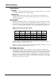
• EWT is less than the Evap Freeze set point minus 0.6 °C and EWT sensor fault
isn’t active
The control state is Run when the flow switch input has been closed for a time greater
than the Evaporator Recirculate set point.
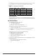
Pump Selection
The pump output used is determined by the Evap Pump Control set point. This setting
allows the following configurations:
• #1 only – Pump 1 will always be used
• #2 only – Pump 2 will always be used
• Auto – The primary pump is the one with the least run hours, the other is used
as a backup
• #1 Primary – Pump 1 is used normally, with pump 2 as a backup
• #2 Primary – Pump 2 is used normally, with pump 1 as a backup
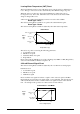
Primary/Standby Pump Staging
The pump designated as primary will start first. If the evaporator state is start for a time
greater than the recirculate timeout set point and there is no flow, then the primary pump
will shut off and the standby pump will start. When the evaporator is in the run state, if
flow is lost for more than half of the flow proof set point value, the primary pump will
shut off and the standby pump will start. Once the standby pump is started, the flow loss
alarm logic will apply if flow cannot be established in the evaporator start state, or if
flow is lost in the evaporator run state.
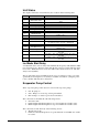
Auto Control
If auto pump control is selected, the primary/standby logic above is still used. When the
evaporator is not in the run state, the run hours of the pumps will be compared. The
pump with the least hours will be designated as the primary at this time.
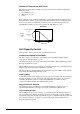
Noise Reduction
Noise Reduction is enabled only when the Noise Reduction set point is enable. Noise
Reduction is in effect when enabled via the set point, the unit mode is cool, and the unit
controller clock time is between the Noise Reduction start time and end time.
When Noise Reduction is in effect, the Maximum Reset is applied to the cool LWT set
point. However, if any reset type is selected, that reset will continue to be used rather
than the maximum reset. Also, the saturated condenser target for each circuit will be
offset by the Noise Reduction Condenser Target Offset.
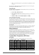
Leaving Water Temperature (LWT) Reset
LWT Target
The LWT Target varies based on settings and inputs and is selected as follows:
Control Source
Set Point
Mode
Input
BAS
Request
Available Modes
Set Point
Base LWT Target
Local OFF X COOL Cool Set Point 1
Local ON X COOL Cool Set Point 2
Network X X COOL BAS Cool Set Point
Local OFF X COOL w/Glycol Cool Set Point 1
Local ON X COOL w/Glycol Cool Set Point 2
Network X X COOL w/Glycol BAS Cool Set Point
Local OFF x COOL/ICE w/Glycol Cool Set Point 1
Local ON x COOL/ICE w/Glycol Ice Set Point
Network x COOL COOL/ICE w/Glycol BAS Cool Set Point
Network x ICE COOL/ICE w/Glycol BAS Ice Set Point
Local x x ICE w/Glycol Ice Set Point
Network x x ICE w/Glycol BAS Ice Set Point