
Troubleshooting guide


Page 22 of 28 / OM 931-3
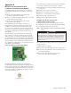
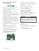
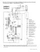
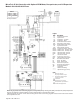
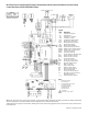
MicroTech III Unit Controller with Optional ECM Motor, Desuperheater and I/O Expansion
Module – 208/230/265/277/60 Hz/1-Phase
T
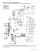
able B
208V
RED
230V
ORG
265V
BRN
277V
BRN
*Drawing No. 668991501
Note: The gray tinted areas in the wiring diagram; Leaving Water (LWT), Discharge Air (DAT) and Return Air (RAT) Temperature
sensors are shipped or are eld installed on units congured with a communication module.
*Wiring diagrams are typical. For the latest drawing version refer to the wiring diagram located on the inside of the controls
access panel of the unit.
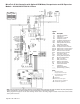
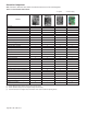
Legend
Item
Description
C1
Capacitor-Compressor
C2
Capacitor-Fan
CC
Compressor - Contactor
CM
Compressor - Motor
CDS
Condensate Overow Sensor
DA
T
Discharge Air Temp Sensor
EWT
Entering Water Temp Sensor
HP
High Pressure Switch
HTR
Electric Heater Cartridge
IOEXP
I/O Expansion Board / Harness
ISO-NC
Isolation V
alve - Normally Closed
ISO-NO
Isolation V
alve - Normally Open
LED1
LED
Annunciator / Harness
LED2
LED
Annunciator / Harness
LP
Low Pressure Switch
SL
TS
Suction Line
Temp Sensor
LWT
Leaving W
ater Temp Sensor
MIII
MicroT
ech III Main Board
R1
Relay - Fan Motor
R2
Relay - Electric Heat
RA
T
Return
Air Temp Sensor
RV
Reversing V
alve Solenoid
TB1
Power
Terminal Block
X1
T
ransformer
_____
Standard Unit Wiring
_ _ _ _
Optional Wiring (by others)
Notes:
1.
Main board jumpers:
No jumpers shorted.
All open.
2.
I/O expansion board jumpers:
Jumper JP4 shorted.
T
ransformer:
Unused wire to be capped.
Desuperheater only available on
1
15-208-230V applications.