
Troubleshooting guide


Page 24 of 28 / OM 931-3
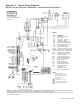
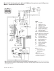
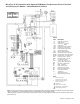
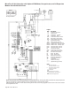
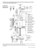
MicroTech III Unit Controller with Optional ECM Motor, Desuperheater, and I/O Expansion
Module 208/230/460/60/3-Phase
*Drawing No. 668991401
Note: The gray tinted areas in the wiring diagram; Leaving Water (LWT), Discharge Air (DAT) and Return Air (RAT) Temperature
sensors are shipped or are eld installed on units congured with a communication module.
*Wiring diagrams are typical. For the latest drawing version refer to the wiring diagram located on the inside of the controls
access panel of the unit.
T
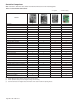
able B
208V
RED
230V
ORG
460V
BLK/RED
Legend
Item
Description
C1
Capacitor-Compressor
C2
Capacitor-Fan
CC
Compressor - Contactor
CM
Compressor - Motor
CDS
Condensate Overow Sensor
DA
T
Discharge Air Temp Sensor
EWT
Entering Water Temp Sensor
HP
High Pressure Switch
HTR
Electric Heater Cartridge
IOEXP
I/O Expansion Board / Harness
ISO-NC
Isolation V
alve - Normally Closed
ISO-NO
Isolation V
alve - Normally Open
LED1
LED
Annunciator / Harness
LED2
LED
Annunciator / Harness
LP
Low Pressure Switch
SL
TS
Suction Line
Temp Sensor
LWT
Leaving W
ater Temp Sensor
MIII
MicroT
ech III Main Board
R1
Relay - Fan Motor
R2
Relay - Electric Heat
RA
T
Return
Air Temp Sensor
RV
Reversing V
alve Solenoid
TB1
Power
Terminal Block
X1
T
ransformer
_____
Standard Unit Wiring
_ _ _ _
Optional Wiring (by others)
Notes:
1.
Main board jumpers:
No jumpers shorted.
All open.
2.
I/O expansion board jumpers:
Jumper JP4 shorted.
T
ransformer:
Unused wire to be capped.
Desuperheater only available on
1
15-208-230V applications.