Operations Manual Daikin MD5 Variable Frequency Drive Controller © 2013 Daikin Applied OM 1191 Group: AAH Part Number: OM 1191 Date: February 2013
Table of Contents Safety . . . . . . . . . . . . . . . . . . . . . . . . . . . . . . . . . . . . . . 4 Embedded Fieldbus . . . . . . . . . . . . . . . . . . . . . . . . . 45 Use of Warnings and Notes . . . . . . . . . . . . . . . . . . . . 4 Overview . . . . . . . . . . . . . . . . . . . . . . . . . . . . . . . . . 45 Control Panel . . . . . . . . . . . . . . . . . . . .
Table of Contents Fieldbus Adapter . . . . . . . . . . . . . . . . . . . . . . . . . . . . 67 Technical Data . . . . . . . . . . . . . . . . . . . . . . . . . . . . . . 82 Overview . . . . . . . . . . . . . . . . . . . . . . . . . . . . . . . . . 67 Ratings . . . . . . . . . . . . . . . . . . . . . . . . . . . . . . . . . . . 82 Control interface . . . . . . . . . . . .
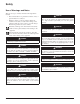
Safety Safety Use of Warnings and Notes There are two types of safety instructions throughout this manual: • Notes draw attention to a particular condition or fact, or give information on a subject. • Warnings caution you about conditions which can result in serious injury or death and/or damage to the equipment. They also tell you how to avoid the danger.
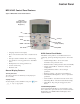
Control Panel Control Panel MD5 HVAC Control Panel Features Figure 1: MD5 HVAC Control Panel Features Status LED (Green when normal, if flashing or red,see Diagnostics.
Control Panel Control Panel Status Information Operating the Drive Top. The top line of the LCD display shows the basic status Auto/Hand – The very first time the drive is powered up, it is in the auto control (AUTO) mode, and is controlled from the Control terminal block X1. information of the drive. • HAND – Indicates that the drive control is local, that is, from the control panel. • AUTO – Indicates that the drive control is remote, such as the basic I/O (X1) or fieldbus.
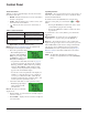
Control Panel Figure 2: Parameters Mode To change the parameters, follow these steps: 1 Select MENU to enter the main menu. 2 Select the Parameters mode with the UP/ DOWN buttons, and select ENTER to select the Parameters Mode. 3 Select the appropriate parameter group with the UP/ DOWN buttons and select SEL. 4 Select the appropriate parameter in a group with the UP/ DOWN buttons. Select EDIT to change the parameter. 5 Press the UP/DOWN buttons to change the parameter value.
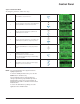
Start Up Start Up Figure 3: Start-Up By Changing the Parameters Individually To change the parameters, follow these steps: 1 Select MENU to enter the main menu. 2 Select the Parameters mode with the UP/DOWN buttons and select ENTER to select the Parameters mode. 3 Select the appropriate parameter group with the UP/ DOWN buttons and select SEL 4 Select the appropriate parameter in a group with the UP/ DOWN buttons. Select EDIT to change the parameter value.
Application Macros Application Macros Overview Macros change a group of parameters to new, predefined values designed for specific applications. Use macros to minimize the need for manual editing of parameters.
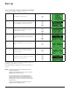
Application Macros Application Macros Figure 4: Selecting an application macro To select a macro, follow these steps: 1 Select MENU to enter the main menu. 2 Select ASSISTANTS with the UP/DOWN buttons and select ENTER. 3 Scroll to APPLICATION and select ENTER. 4 Select a macro with the UP/DOWN buttons and select SAVE. Restoring defaults To restore the factory default settings, select the application macro HVAC Default. Control wiring Each macro has specific requirements for control wiring.
Application Macros HVAC Default macro This macro provides the factory default parameter settings for the MD5-UH. Factory defaults can be restored at any time by setting parameter 9902 to 1. The diagram below shows typical wiring using this macro. When using direct speed reference in AUTO mode or process PID, see General Considerations on page 9.
Parameters Parameters Parameter List The following parameters are important on Daikin applications. A summary is shown in Table 63: Parameter Settings on page 89. All other should not be adjusted. Parameter data is specific to MD5 firmware version 2.13. Group 99: Start-Up Data NOTE: Parameters checked under the heading “S” can be modified only when the drive is stopped. This group defines special Start-up data required to: • Set up the drive.
Parameters Parameters Group 01: Operating Data This group contains drive operating data, including actual signals. The drive sets the values for actual signals, based on measurements or calculations. You cannot set these values. Table 5: Group 01: Operating Data Code 0101 Description SPEED & DIR Range Resolution Default -30000… 30000 rpm 1 rpm — S The calculated signed speed of the motor (rpm). The absolute value of 0101 SPEED & DIR is the same as the value of 0102 SPEED.
Parameters Table 5 continued: Group 01: Operating Data 0118 DI 1-3 STATUS 000…111 (0…7 decimal) 1 — 000…111 (0…7 decimal) 1 — 0.0…100.0% 0.1% — 0.0…100.0% 0.1% — 000…111 (0…7 decimal) 1 — 000…111 (0…7 decimal) 1 — 0.0…20.0 mA 0.1 mA — 0.0…20.0 mA 0.1 mA — -1000.0… 1000.0% 0.1% — -100.0… 100.0% 0.1% — Unit and scale defined by par. 4006/4106 and 4007/4107 — — Unit and scale defined by par. 4206 and 4207 — — Unit and scale defined by par.
Parameters Table 5 continued: Group 01: Operating Data 0131 PID 2 FBK Unit and scale defined by par. 4206 and 4207 — — Unit and scale defined by par. 4006/4106 and 4007/4107 — — Unit and scale defined by par. 4206 and 4207 — — 0…65535 1 — -32768… +32767 1 — -32768… +32767 1 — — 1 — — 1 — — 1 — 0.00…499.99 kh 0.01 kh — 0…65535 MWh 1 MWh — 1 Mrev — 0…65535 days 1 day — 00:00:00… 23:59:58 1=2s — The PID 2 controller feedback signal.
Parameters Table 5 continued: Group 01: Operating Data 0145 MOTOR TEMP Par. 3501 = 1…3: -10…200 °C Par. 3501 = 4: 0…5000 ohm Par. 3501 = 5…6: 0…1 1 — -20.0… 150.0 °C 1.0 °C — Motor temperature in degrees Celsius / PTC resistance in ohms. • Applies only if motor temperature sensor is set up. 0150 CB TEMP Temperature of the drive control board in degrees Celsius. Note: Some drives have a control board (OMIO) that does not support this feature. These drives always show the constant value of 25.0 °C.
Parameters Group 03: Actual Signals This group monitors fieldbus communications. Table 6: Group 03: Actual Signals Code Description 0301 FB CMD WORD 1 Range Resolution Default — 1 — S Read-only copy of the Fieldbus Command Word 1. • The fieldbus command is the principal means for controlling the drive from a fieldbus controller. The command consists of two Command Words. Bit-coded instructions in the Command Words switch the drive between states.
Parameters Table 6 continued: Group 03: Actual Signals 0305 FAULT WORD 1 — 1 — Read-only copy of the Fault Word 1. • When a fault is active, the corresponding bit for the active fault is set in the Fault Words. • Each fault has a dedicated bit allocated within Fault Words. • See section Fault listing on page 1-282 for a description of the faults. • The control panel displays the word in hex. For example, all zeros and a 1 in Bit 0 displays as 0001. All zeros and a 1 in Bit 15 displays as 8000.
Parameters Group 04: Fault History This group stores a recent history of the faults reported by the drive. Table 7: Group 04: Fault History Code 0401 Description Range Resolution Default LAST FAULT Fault codes (panel displays as text) 1 0 S 0 – Clear the fault history (on panel = NO RECORD). n – Fault code of the last recorded fault. The fault code is displayed as a name. See section Fault listing on page 1-282 for the fault codes and names.
Parameters Group 10: Start/Stop/Dir This group: • Defines external sources (EXT1 and EXT2) for commands that enable start, stop and direction changes • Locks direction or enables direction control. To select between the two external locations use the next group (parameter 1102). Table 8: Group 10: Start/Stop/Dir Code Description Range Resolution Default S 1001 EXT1 COMMANDS 0…14 1 1 (DI1) Defines external control location 1 (EXT1) – the configuration of start, stop and direction commands.
Parameters Group 11: Reference Select This group defines: • How the drive selects between command sources • Characteristics and sources for REF1 and REF2. Table 9: Group 11: Reference Select Code Description Range Resolution Default S 1102 EXT1/EXT2 SEL -6…12 1 0 (EXT1) Defines the source for selecting between the two external control locations EXT1 or EXT2. Thus, defines the source for Start/Stop/Direction commands and reference signals.
Parameters Table 9 continued: Group 11: Reference Select 1103 0…17, 20…21 REF1 SELECT 1 1 (AI1) Selects the signal source for external reference REF1. 0 = KEYPAD – Defines the control panel as the reference source. 1 = AI1 – Defines analog input 1 (AI1) as the reference source. 2 = AI2 – Defines analog input 2 (AI2) as the reference source. 3 = AI1/JOYST – Defines analog input 1 (AI1), configured for joystick operation, as the reference source.
Parameters Table 9 continued: Group 11: Reference Select 1104 REF1 MIN 0.0…500.0 Hz / 0…30000 rpm 0.1 Hz / 1 rpm 0.0 Hz / 0 rpm Sets the minimum for external reference 1. • The minimum analog input signal (as a percent of the full signal in volts or amperes) corresponds to REF1 MIN in Hz/rpm. •Parameter 1301 MINIMUM AI1 or 1304 MINIMUM AI2 sets the minimum analog input signal. Does not apply to Daikin MicroTech III applications. • These parameters (reference and analog min. and max.
Parameters Group 12: Constant Speeds This group defines a set of constant speeds. In general: • You can program up to 7 constant speeds, ranging from 0…500 Hz or 0…30000 rpm. • Values must be positive (No negative speed values for constant speeds). • Constant speed selections are ignored if: – The torque control is active, or – The process PID reference is followed, or – The drive is in local control mode, or – PFA (Pump-Fan Alternation) is active.
Parameters Table 10 continued: Group 12: Constant Speeds Code Description Range Resolution Default S 1, 2 1 2 (CS1/2/3/4) -7 = DI1,2(INV) – Selects one of three Constant Speeds (1…3) using DI1 and DI2.
Parameters Group 16: System Controls This group defines a variety of system level locks, resets and enables. Table 11: Group 16: System Controls Code 1601 Description RUN ENABLE Range Resolution Default S 1 0 (NOT SEL) -6…7 Selects the source of the run enable signal. 0 = NOT SEL – Allows the drive to start without an external run enable signal. 1 = DI1 – Defines digital input DI1 as the run enable signal. • This digital input must be activated for run enable.
Parameters Table 11 continued: Group 16: System Controls 1608 START ENABLE 1 -6…7 1 4 (DI4) Selects the source of the start enable 1 signal. Note: Start enable functionality differs from the run enable functionality. 0 = NOT SEL – Allows the drive to start without an external start enable signal. 1 = DI1 – Defines digital input DI1 as the start enable 1 signal. • This digital input must be activated for start enable 1 signal.
Parameters Group 20: Limits This group defines minimum and maximum limits to follow in driving the motor –speed, frequency, current, torque, etc. Table 12: Group 20 — Limits Code Name 2001 MINIMUM SPEED Range Resolution Default -30000…30000 rpm 1 rpm 0 rpm User S 0…30000 rpm 1 rpm 1800 rpm (US) 0… 1.3 · I2n 0.1 A 1.3 · I2n 0…2 1 1 [ENABLE(TIME)] Defines the minimum speed (rpm) allowed. • A positive (or zero) minimum speed value defines two ranges, one positive and one negative.
Parameters Group 21: Start/Stop This group defines how the motor starts and stops. The MD5 supports several start and stop modes. Table 13: Group 21: Start/Stop Code 2101 Description START FUNCTION Range Resolution Default S 1 3 (SCALAR FLYST) Vector control modes: 1, 2, 8 Scalar control mode: 1…5, 8 Selects the motor start method . The valid options depend on the value of parameter 9904 MOTOR CTRL MODE . Does not apply to Daikin MicroTech III applications.
Parameters Group 22: Accel/Decel This group defines ramps that control the rate of acceleration and deceleration. You define these ramps as a pair, one for acceleration and one for deceleration. You can define two pairs of ramps and use a digital input to select one or the other pair. Table 14: Group 22: Accel/Decel Code 2202 Description ACCELER TIME 1 Range Resolution Default 0.0… 1800.0 s 0.1 s 30.0 s 0.0… 1800.0 s 0.1 s 30.
Parameters Group 26: Motor Control This group defines variables used for motor control. Table 15: Group 26: Motor Control Code 2605 Description U/f RATIO Range 1, 2 Resolution Default 1 2 (SQUARED) S Selects the form for the U/f (voltage to frequency) ratio below field weakening point. 1 = LINEAR – Preferred for constant torque applications. 2 = SQUARED – Preferred for centrifugal pump and fan applications. (SQUARED is more silent for most operating frequencies.
Parameters Group 30: Fault Functions This group defines situations that the drive should recognize as potential faults and defines how the drive should respond if the fault is detected. Table 16: Group 30: Fault Functions Code 3003 Description EXTERNAL FAULT 1 Range Resolution Default 1 0 (NOT SEL) -6…6 S Defines the External Fault 1 signal input and the drive response to an external fault. 0 = NOT SEL – External fault signal is not used.
Parameters Group 31: Automatic Reset This group defines conditions for automatic resets. An automatic reset occurs after a particular fault is detected. The drive holds for a set delay time, then automatically restarts. You can limit the number of resets in a specified time period and set up automatic resets for a variety of faults.
Parameters Group 34: Panel Display This group defines the content for control panel display (middle area), when the control panel is in the Output mode. Table 18: Group 34: Panel Display Code 3401 Description Range SIGNAL1 PARAM Resolution Default 100…178 1 103 (OUTPUT FREQ) 0…9 1 5 (+0.0) S Selects the first parameter (by number) displayed on the control panel. • Definitions in this group define display content when the control panel is in the control mode.
Parameters Table 19 continued: Group 34: Panel Display 3407 OUTPUT1 MAX Depends on selection — 1000.0 (%SP) 100…178 1 104 100…178 1 120 (AI 1) 0…9 1 5 (+0.0) Sets the maximum value displayed for the first display parameter. Note: Parameter is not effective if parameter 3404 OUTPUT1 DSP FORM = 9 (DIRECT). 3408 SIGNAL 2 PARAM Selects the second parameter (by number) displayed on the control panel. See parameter 3401.
Parameters Group 36: Timed Functions This group defines the timed functions. The timed functions include: • Four daily start and stop times • Four weekly start, stop and boost times • Four timers for collecting selected periods together. A timer can be connected to multiple time periods and a time period can be in multiple timers. A parameter can be connected to only one timer.. You can use the Timed functions assistant for easy configuring.
Parameters Table 19 continued: Group 36: Timed Functions 3603 STOP TIME 1 00:00:00…23:59:58 2s 12:00:00 AM 1…7 1 1 (MONDAY) 1…7 1 1 (MONDAY) 00:00:00…23:59:58 2s 12:00:00 AM 00:00:00…23:59:58 2s 12:00:00 AM 1…7 1 1 (MONDAY) 1…7 1 1 (MONDAY) 00:00:00…23:59:58 2s 12:00:00 AM 00:00:00…23:59:58 2s 12:00:00 AM 1…7 1 1 (MONDAY) 1…7 1 1 (MONDAY) 00:00:00…23:59:58 2s 12:00:00 AM 00:00:00…23:59:58 2s 12:00:00 AM 1…7 1 1 (MONDAY) 1…7 1 1 (MONDAY) -6…6 1 0 (NOT SEL) 00
Parameters Group 53: EFB Protocol This group defines set-up variables used for an embedded fieldbus (EFB) communication protocol. The standard EFB protocol in the MD5 is Modbus. See chapter Embedded Fieldbus on page 45. Table 20: Group 53: EFB Protocol Code 5302 Description EFB STATION ID Range Resolution Default S 0…65535 1 = SAF 2 = RAF/EAF 3 = ERW 1 1.2, 2.4, 4.8, 9.6, 19.2, 38.4, 57.6, 76.8 kb/s — 9.
Parameters Group 64: Load Analyzer This group defines the load analyzer, which can be used for analyzing the customer’s process and sizing the drive and the motor. The peak value is logged at 2 ms level, and the distribution loggers are updated on 0.2 s (200 ms) time level. Three different values can be logged. 1. Amplitude logger 1: The measured current is logged continuously. The distribution as a percentage of the nominal current I2n is shown in ten classes. 2.
Parameters Table 21 continued: Group 64: Load Analyzer 6411 FREQ AT PEAK 0.0…6553.5 Hz 0.1 Hz — Date dd.mm.yy / power-on time in days 1d — Output frequency at the moment of the peak value (herzes). 6412 TIME OF RESET 1 Last reset date of the peak logger and amplitude logger 2. • Format: Date if the real time clock is operating (dd.mm.yy). / The number of days elapsed after the power-on if the real time clock is not used, or was not set (xx d). 6413 TIME OF RESET 2 Time hh.mm.ss 2s — 0.0…100.
Parameters Group 81: PFA Control Table 22: Group 81: PFA Control Code Description 8120 INTERLOCKS Range Resolution Default S 0…6 1 4 (DI4) Defines operation of the Interlock function. When the Interlock function is enabled: • An interlock is active when its command signal is absent. • An interlock is inactive when its command signal is present. • The MD5 will not start if a start command occurs when the speed regulated motor’s interlock is active – the control panel displays an alarm.
Parameters Table 22 continued: Group 81: PFA Control 2 = DI2 – Enables the Interlock function and assigns a digital input (starting with DI2) to the interlock signal for each PFA relay. These assignments are defined in the following table and depend on: • the number of PFA relays [number of parameters 1401…1403 and 1410…1412 with value = 31 (PFA)] • the Autochange function status (disabled if 8118 AUTOCHNG INTERV = 0.0, and otherwise enabled). No.
Parameters Table 22 continued: Group 81: PFA Control 4 = DI4 – Enables the Interlock function and assigns a digital input (starting with DI4) to the interlock signal for each PFA relay. These assignments are defined in the following table and depend on: • the number of PFA relays [number of parameters 1401…1403 and 1410…1412 with value = 31 (PFA)] • the Autochange function status (disabled if 8118 AUTOCHNG INTERV = 0.0, and otherwise enabled). No.
Parameters Group 98: Options This group configures for options, in particular, enabling serial communication with the drive. Table 23: Group 98: Options Code 9802 Description COMM PROT SEL Range 0…5 Resolution Default S 1 0 (NOT SEL) Selects the communication protocol. 0 = NOT SEL – No communication protocol selected. 1 = STD MODBUS – The drive communicates with Modbus via the RS485 channel (X1-communications, terminal). • See also Group 53: EFB PROTOCOL.
Embedded Fieldbus Embedded Fieldbus Overview The MD5 can be set up to accept control from an external system using standard serial communication protocols. When using serial communication, the ACH550 can either: • Receive all of its control information from the fieldbus, or • Be controlled from some combination of fieldbus control and other available control locations, such as digital or analog inputs, and the control panel.
Embedded Fieldbus Embedded Fieldbus Mechanical and Electrical Installation–EFB WARNING Connections should be made only while the drive is disconnected from the power source. • Use Belden 9842 or equivalent. Belden 9842 is a dual twisted, shielded pair cable with a wave impedance of 120 Ω. • Use one of these twisted shielded pairs for the RS485 link. Use this pair to connect all A (-) terminals together and all B (+) terminals together.
Embedded Fieldbus Figure 8: Alternate Wiring Diagram OM 1191 47
Embedded Fieldbus Communication Setup – EFB Serial Communication Selection Serial Communication Configuration To activate the serial communication, set parameter 9802 COMM PROTOCOL SEL = Setting 9802 automatically sets the appropriate default values in parameters that define the communication process. These parameters and descriptions are defined below. In particular, note that the station ID may require adjustment. • • • • 1 (STD MODBUS).
Embedded Fieldbus Table 23 continued: Serial Communication Configuration Code Description EFB Protocol Reference Modbus N2 FLN BACnet EFB CTRL PROFILE Selects the communication profile used by the EFB protocol. 0 = Daikin DRV LIM – Operation of Control/ . 5305 1 = DCU PROFILE – Operation of Control/Status Words conform to 32-bit DCU Profile. 2 = Daikin DRV FULL – Operation of Control/Status Words conform to Daikin Drives Profile (full).
Embedded Fieldbus Activate Drive Control Functions – EFB Controlling the Drive Start/Stop Direction Control Fieldbus control of various drive functions requires configuration to: Using the fieldbus for start/stop/direction control of the drive requires: • Tell the drive to accept fieldbus control of the function. • Define as a fieldbus input, any drive data required for control. • Define as a fieldbus output, any control data required by the drive.
Embedded Fieldbus Miscellaneous Drive Control Using the fieldbus for miscellaneous drive control requires: • Drive parameter values set as defined below. • Fieldbus controller supplied reference word(s) in the appropriate location. (The location is defined by the Protocol Reference, which is protocol dependent.) Table 26: Miscellaneous Drive Control Parameters Protocol Reference Drive Parameter Value Setting 7 (COMM) (Not Run enable by Recommended) fieldbus.
Embedded Fieldbus Relay Output Control Using the fieldbus for relay output control requires: • Drive parameter values set as defined below. • Fieldbus controller supplied reference word(s) in the appropriate location. (The location is defined by the Protocol Reference, which is protocol dependent.) For example: To control relays 1 and 2 using serial communication: Set parameters 1401 RELAY OUTPUT 1 and 1402 RELAY OUTPUT 1 = 35 (COMM).
Embedded Fieldbus Analog Output Control Using the fieldbus for analog output control requires: • Drive parameter values set as defined below. • Fieldbus controller supplied reference word(s) in the appropriate location. (The location is defined by the Protocol Reference, which is protocol dependent.
Embedded Fieldbus Feedback from the Drive – EFB Pre-Defined Feedback Inputs to the controller (drive outputs) have pre-defined meanings established by the protocol. This feedback does not require drive configuration. The following table lists a sample of feedback data. NOTE: With Modbus, any parameter can be accessed using the format: 4 followed by the parameter number.
Embedded Fieldbus Actual Value Scaling The scaling of actual values can be protocol dependent. In general, for Actual Values, scale the feedback integer using the parameter’s resolution. For example: Feedback Integer Parameter Resolution (Feedback Integer) × (Parameter Resolution) = Scaled Value 1 0.1 mA 1 × 0.1 mA = 0.1 mA 10 0.1% 10 × 0.1% = 1% Where parameters are in percent, the Complete parameter descriptions section specifies what parameter corresponds to 100%.
Embedded Fieldbus Diagnostics – EFB Fault Queue for Drive Diagnostics For general MD5 diagnostics information, see Diagnostics on page 74. The three most recent MD5 faults are reported to the fieldbus as defined below. For specific MD5 fault codes, see Table 53: Fault Listing on page 75.
Embedded Fieldbus Duplicate Stations Fault 31 – EFB1 If two or more stations have duplicate numbers: For BACnet: If the drive’s control panel shows fault code 31 “EFB1”, the drive has an invalid Device Object Instance ID. To correct, use parameters 5311 and 5317 and establish a unique drive ID that is in the range 1 to 4,194,303. • Two or more drives cannot be addressed. • Every time there is a read or write to one particular station, the value for 5307 EFB CRC ERRORS or 5308 EFB UART ERRORS advances.
Embedded Fieldbus Troubleshooting The troubleshooting table below should be followed in order from top to bottom by parameter number. Begin the troubleshooting process by displaying the first parameter in the table (5308) and determining if the display on the panel exhibits the symptom. If it does, review the possible cause(s) and take the necessary corrective action(s). Once the symptom for this parameter is eliminated, continue to the next parameter and repeat the process until you have reached the end.
Embedded Fieldbus BACnet Protocol Technical Data Binary Input Object Instance Summary The following table summarizes the Binary Input Objects supported: Table 35: Binary Input Objects Instance ID Object Name Active/Inactive Text Present Value Access Type BI0 RO 1 ACT This object indicates the status of Relay Output 1. Description ON/OFF R BI1 RO 2 ACT This object indicates the status of Relay Output 2. ON/OFF R BI2 RO 3 ACT This object indicates the status of Relay Output 3.
Embedded Fieldbus Binary Value Object Instance Summary The following table summarizes the Binary Value Objects supported: Table 37: Binary Value Objects Active/Inactive Text Present Value Access Type This object indicates the drive Run Status, regardless of the control source. RUN/STOP R This object indicates the motor’s rotation direction, regardless of the control source. REV/FWD R FAULT ACT this object indicates the drive’s fault status.
Embedded Fieldbus Analog Output Object Instance Summary The following table summarizes the Analog Output Objects supported: Table 39: Analog Output Objects Instance ID Object Name Description Units Present Value Access Type AO0 AO 1 COMMAND This object controls Analog Output 1. The corresponding drive parameter is 0135, COMM VALUE 1. Control requires parameter 1501 value = 135. Percent C AO 2 COMMAND This object controls Analog Output 2. The corresponding drive parameter is 0136, COMM VALUE 2.
Embedded Fieldbus AV26 MBOX DATA AV27 EXT PID STPT This object holds the mailbox function’s parameter value – a value that was read, or is to be written. See BV15 and BV16. This object sets the External PID controller setpoint. The corresponding drive parameter is 4211. Control requires parameter 4210, PID SETPOINT SEL, value = 19 (INTERNAL). None W Percent C NOTE: For Present Value Access Types, R = Read-only, W = Writeable, C = Commandable.
Embedded Fieldbus BACnet Device Address Rules • MSTP MAC Addresses must be unique for all devices connected to the same RS485 network. • MSTP MAC Address is configurable via parameter 5302 in MD5. 1..127 = range of supported Master addresses for MD5 • Network Number must be unique for each network (IP and MSTP) • Network Number of 0 is reserved for broadcasts • Device Object IDs must be unique across the entire BACnet network, all IP and MSTP subnetworks.
Embedded Fieldbus Protocol Implementation Conformance Statement (PICS) PICS Summary BACnet Standard Device Profile. This version of MD5 BACnet fully conforms to the ‘Application-Specific Controller’ standard device profile (B-ASC). Services Supported. The following services are supported by the MD5: • I-Am (Response to Who-Is, also broadcast on power-up & other reset) • I-Have (Response to Who-Has) • ReadProperty • WriteProperty • DeviceCommunicationControl • ReinitializeDevice Data Link Layer.
Embedded Fieldbus Statement This statement is part of this Standard and is required for its use. Table 41: BACnet Protocol Implementation Conformance Statement Date: February 5, 2009 Vendor Name: Daikin Product Name: Low Voltage AC Motor Drive Product Model Number: MD5 Applications Software Version: 050F Firmware Revision: 312B BACnet Protocol Revision: 4 Product Description: The MD5 is a high-performance adjustable frequency drive specifically designed for commercial automation applications.
Embedded Fieldbus BACnet Object Definitions Object/Property Support Matrix The following table summarizes the Object Types/Properties Supported: Table 42: BACnet Objects Property Object Type Device Binary Input Binary Output Binary Value Analog Input Analog Output Analog Value * * Object Identifier Object Name Object Type System Statu
Fieldbus Adapter Fieldbus Adapter Overview The MD5 can be set up to accept control from an external system using standard serial communication protocols. When using serial communication, the MD5 can either: • Receive all of its control information from the fieldbus, or • Be controlled from some combination of fieldbus control and other available control locations, such as digital or analog inputs, and the control panel.
Fieldbus Adapter Fieldbus Adapter Control Word Actual Values The CONTROL WORD is the principal means for controlling the drive from a fieldbus system. The fieldbus controller sends the CONTROL WORD to the drive. The drive switches between states according to the bit-coded instructions in the CONTROL WORD. Using the CONTROL WORD requires that: Actual Values are 16-bit words containing information on selected operations of the drive.
Fieldbus Adapter Communication Setup – FBA Serial Communication Selection Activate Drive Control Functions – FBA To activate the serial communication, use parameter 9802 COMM PROTOCOL SEL. Set 9802 = 4 (EXT FBA). Fieldbus control of various drive functions requires configuration to: Serial communication configuration Setting 9802, together with mounting a particular FBA module, automatically sets the appropriate default values in parameters that define the communication process.
Fieldbus Adapter System Control Using the fieldbus for miscellaneous drive control requires: • Drive parameter values set as defined below. • Fieldbus controller command(s) in the appropriate location. (The location is defined by the Protocol Reference, which is protocol dependent.) Table 45: Fieldbus Controller Commands Value Description 1601 Drive Parameter RUN ENABLE 7 (COMM) Run enable by fieldbus. 1604 FAULT RESET SEL 8 (COMM) Fault reset by fieldbus.
Fieldbus Adapter PID Control Setpoint Source Using the fieldbus for the PID control setpoint requires: • Drive parameter values set as defined below. • Fieldbus controller supplied setpoint value in the appropriate location. (As defined in Analog output control above.
Fieldbus Adapter Diagnostics – FBA Fault Handling Serial Communication Diagnostics The MD5 provides fault information as follows: Besides the drive fault codes, the FBA module has diagnostic tools. Refer to the user’s manual supplied with the FBA module. • The control panel display shows a fault code and text. See page 74 for a complete description. • Parameters 0401 LAST FAULT, 0402 PREVIOUS FAULT1 and 0403 PREVIOUS FAULT2 store the most recent faults.
Fieldbus Adapter Generic Profile Technical Data Overview Reference The generic profile aims to fulfill the industry-standard drive profile for each protocol (e.g. PROFIdrive for PROFIBUS, AC/DC Drive for DeviceNet). As described earlier in Control interface, the REFERENCE word is a speed or frequency reference. Control Word Reference Scaling As described earlier in Control interface the CONTROL WORD is the principal means for controlling the drive from a fieldbus system.
Diagnostics Diagnostics WARNING Do not attempt any measurement, parts replacement or other service procedure not described in this manual. Such action will void the warranty, may endanger correct operation, and increase downtime and expense. DANGER All electrical installation and maintenance work described in this chapter should only be undertaken by qualified service personnel. The Safety instructions on the first pages of this manual must be followed.
Diagnostics Diagnostics Correcting Faults The recommended corrective action for faults is: • Use the Fault listing table below to find and address the root cause of the problem. • Reset the drive. See Fault Resetting on page 78. Table 53: Fault Listing Fault Code Fault Name In Panel Description and Recommended Corrective Action 1 OVERCURRENT Output current is excessive. Check for and correct: • Excessive motor load. • Insufficient acceleration time (parameters 2202 ACCELER TIME 1).
Diagnostics Table 53 continued: Fault Listing Fault Code Description and Recommended Corrective Action Possible ground fault detected in the motor or motor cables. The drive monitors for ground faults while the drive is running and while the drive is not running. Detection is more sensitive when the drive is not running and can produce false positives. Possible corrections: • Check for/correct faults in the input wiring. • Verify that motor cable does not exceed maximum specified length.
Diagnostics Table 53 continued: Fault Listing Fault Code Fault Name In Panel 101 SERF CORRUPT 102 RESERVED 103 SERF MACRO 104 RESERVED 105 RESERVED 201 DSP T1 OVERLOAD 202 DSP T2 OVERLOAD 203 DSP T3 OVERLOAD 204 DSP STACK ERROR 205 RESERVED (obsolete) 206 OMIO ID ERROR 207 EFB LOAD ERR Description and Recommended Corrective Action . . Parameter values are inconsistent. Check for any of the following: • 2001* MINIMUM SPEED > 2002* MAXIMUM SPEED.
Diagnostics Fault Resetting History The MD5 can be configured to automatically reset certain faults. Refer to parameter Group 31: Automatic Reset on page 33. For reference, the last three fault codes are stored into parameters 0401, 0412, 0413. For the most recent fault (identified by parameter 0401), the drive stores additional data (in parameters 0402…0411) to aid in troubleshooting a problem. For example, parameter 0404 stores the motor speed at the time of the fault.
Diagnostics Table 54 continued: Alarms by Code Numbers Fault Code Fault Name In Panel 2010 MOT OVERTEMP 2011 UNDERLOAD 2012 MOTOR STALL 2013 (note 1) AUTORESET 2014 (note 1) AUTOCHANGE 2015 PFA INTERLOCK 2016 Reserved 2017 OFF BUTTON 2018 (note 1) PID SLEEP 2019 ID RUN 2020 OVERRIDE Description and Recommended Corrective Action Motor is hot, based on either the drive’s estimate or on temperature feedback. This alarm warns that a Motor Underload fault trip may be near.
Maintenance Maintenance WARNING Read Safety on page 1-3 before performing any maintenance on the equipment. Ignoring the safety instructions can cause injury or death. Maintenance Intervals If installed in an appropriate environment, the drive requires very little maintenance. This table lists the routine maintenance intervals recommended by Daikin.
Maintenance Maintenance Figure 12: Drive Module Fan Replacement, R1–R4 Capacitors The drive intermediate circuit employs several electrolytic capacitors. Their life span is from 35,000…90,000 hours depending on drive loading and ambient temperature. Capacitor life can be prolonged by lowering the ambient temperature. It is not possible to predict a capacitor failure. Capacitor failure is usually followed by a input power fuse failure or a fault trip. Contact Daikin if capacitor failure is suspected.
Technical Data Technical Data Ratings By type code, the table below provides ratings for the MD5 adjustable speed AC drive, including: • IEC ratings • NEMA ratings (shaded columns) • Frame size Valid up to 40°C (104 °F) Abbreviated column headers are described in Symbols on page 83. Table 56: Ratings, 208…240 volt drives Valid up to 40°C (104 °F) Pn A HP Frame Size I2n Pn A HP Frame Size Three-phase supply voltage, 380…480 V 3.3 1.5 R1 4.1 2 R1 6.9 3 R1 8.8 5 R1 11.9 7.5 R1 15.
Technical Data Technical Data Ratings, 500…600 volt drives Abbreviated column headers are described in Symbols below. Table 58: Ratings, 500…600 volt drives Type Code ACH550-xxsee below Normal Use I2n Pn A HP Frame Size Three-phase supply voltage, 500…600 V -02A7-6 2.7 2 R2 -03A9-6 3.9 3 R2 -06A1-6 6.1 5 R2 -09A0-6 9 7.
Technical Data Control connections Control Connection Specifications Table 59: Control Connection Specifications Analog Inputs and Outputs See Table 60: Drive Control Terminal Descriptions on page 86. Digital Inputs Digital input impedance 1.5 kΩ. Maximum voltage for digital inputs is 30 V. Control Cables General Recommendations Use multi-core cables with a braided copper wire screen, temperature rated at 60 °C (140 °F) or above: • Max. contact voltage: 30 V DC, 250 V AC • Max.
Technical Data WARNING Relay coils generate noise spikes in response to steps in applied power. To avoid drive damage from such spikes, all AC relay coils mounted across drive inputs require R-C snubbers, and all DC relay coils mounted across drive outputs require diodes – see figure. Drive’s Control Connection Terminals The following table provides specifications for the drive’s control terminals Control Frame Size All Maximum Wire Size Torque mm2 AWG Nm lb-ft 1.5 16 0.4 0.
Technical Data Table 60: Drive Control Terminal Descriptions X1 1 Drive Control Terminal Description SCR Terminal for signal cable screen. (Connected internally to chassis ground.) Analog input channel 1, programmable. Default2 = external reference. Resolution 0.1%, accuracy ±1%. 2 AI1 J1:AI1 OFF: 0(2)…10 V (Ri = 312 kΩ) or, for OFF for ON Analog I/O J1:AI1 ON: 0(4)…20 mA (Ri = 100 Ω) 3 AGND Analog input circuit common (connected internally to chassis gnd. through 1 MΩ).
Technical Data Ambient Conditions The following table lists the MD5 environmental requirements. Table 61: Ambient Environment Requirements Storage and Transportation in the protective package Installation Site Altitude Ambient temperature Relative humidity Contamination Levels (IEC 721-3-3) • 0…1000 m (0…3,300 ft) • 1000…2000 m (3,300…6,600 ft) if Pn and I2 derated 1% every 100 m above 1000 m (300 ft above 3,300 ft) • • • • Min. -15 ºC (5 ºF) – no frost allowed Max.
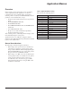
Appendix Appendix Daikin Applications Parameter Settings: The MD5 VFD has been made to Daikin specifications. All factory installed MD5 VFDs with MicroTech III controls are also factory configured and started. Table 63 lists the parameters that have been specifically configured for Daikin or may need owner adjustment as described in this manual. • “HVAC Default” settings mentioned in the Table 63 note is the vendor default if Parameter 9902 is set as shown.
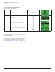
Appendix Appendix Table 63: Parameter Settings RoofPak & Self C Maverick II Maverick II RoofPak Maverick II & Rebel # MD5 Parameters Name Unit SAF, RAF & EAF SAF EAF Ener Rec Wheel Ener Rec Wheel 9802 COMM PROT SEL STD MODBUS STD MODBUS STD MODBUS STD MODBUS STD MODBUS 9901 LANGUAGE ENGLISH ENGLISH ENGLISH ENGLISH ENGLISH 9902 APPLIC MARCO HVAC DEFAULT HVAC DEFAULT HVAC DEFAULT HVAC DEFAULT HVAC DEFAULT 9905 MOTOR NOM VOLT V 575 575 575 575 575 9906 MOTOR NOM CURR
Appendix MicroTech III Control Parameters: The MD5 will be factory configured to work with MicroTech III Controls and factory tested. The downloaded parameters have a high probability of being fully correct if the following parameters are set. • Parameter 9802 states: “STD MODBUS”. • Parameter 1001, 1103, 1601, 1604 and 1608 state: “COMM”. • Parameter 5302 = address 1, 2 or 3 as required by the application. • Parameter 5303 = “192” buad rate (19.2 K Bytes/ second). • Parameter 5304 = “8 NONE 2”.
Appendix MD5 MPS_ SAF-EAF-ERW SCHEMATIC; ALL USE MODBUS CONTROL Figure 14: MD5 Maverick II — Supply Fan, Exhaust Fan and Energy Recovery Wheel No Energy Recovery SAF VFD WHITE BLACK +NB VFD10 VFD51 VFD60 29 A+ BUS TERMINAL * SHOWN AS OM 1191 RJ45 30 BX1A SCR 1 AI1 2 AGND 3 8 REMOTE KEYPAD ALL DRAINS (DRN) 213B-13 213B-14 H213B-3 NOTE: DRN CHANGES.
Appendix MD5 Figure 15:Self-contained MD5 RoofPak and SAF Self-Contained Air Conditioner Supply Air Fan A+1/2.12 WHITE BLACK +NB VFD10 SAF 29 A+ 30 B- SCR MD5 B L A J C K RJ45 2 AGND 3 10V 4 AI2 5 AGND 6 AO1 7 AGND 8 JUMPERS** ma ma 92 DCOM V AI2 WHT BLK +NB SPS1 TB1(-) TB1(+) DRN WHT BLK DUCT STATIC PRESSURE +NB SPS-X TB1(-) TB1(+) 11 YELLOW DI3 12 Jumper to establish digital ground reference to internal 24VDC supply.
Appendix MD5 RoofPak MicroTech III APPLICABLE SAF, EAF AND RAF. Figure 16: MD5 TO RoofPak Condenser Fan Speed Control A+1/2.
Appendix MD5 RoofPak Energy Recovery Wheel, Frost Control Option Figure 17: MD5 RoofPak — Energy Recovery Wheel, Frost Control Option A+1/2.12 WHITE BLACK +NB VFD10 SAF 29 A+ 30 B- SCR MD5 B L A J C K J RJ45 AI1 2 AGND 3 10V 4 AI2 5 AGND 6 AO1 7 AGND 8 GND DCOM 11 YELLOW DI3 12 Jumper to establish digital ground reference to internal 24VDC supply.
Daikin Training and Development Now that you have made an investment in modern, efficient Daikin equipment, its care should be a high priority. For training information on all Daikin HVAC products, please visit us at www.DaikinApplied.com and click on training, or call 540-248-9646 and ask for the Training Department. Warranty All Daikin equipment is sold pursuant to its standard terms and conditions of sale, including Limited Product Warranty. Consult your local Daikin Representative for warranty details.