Installation & Maintenance Data IM 950-1 Group: PTAC Part Number: 669548801 Date: February 2009 PDAE/PDHE 16" x 44" Replacement Unit Comfort Conditioner Note: Installation and maintenance are to be performed only by qualified personnel who are familiar with local codes and regulations and are experienced with this type of equipment. Caution: Sharp edges and coil surfaces are potential injury hazards.
Table of Contents Safety Information........................................................3 Inspection......................................................................3 Nomenclature................................................................4 Dimensional Data........................................................5 Wall Opening Requirements...................................6 Installation Considerations.....................................7 Preparing the Unit for Installation.....................
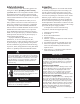
Safety Information Follow all safety codes. Wear safety glasses and work gloves. Use a quenching cloth for brazing operations. Have a fire extinguisher available. Follow all warnings and cautions in these instructions and attached to the unit. Consult applicable local building codes and National Electrical Codes (NEC) for special requirements. Recognize safety information. When you see a safety symbol on the unit or in these instructions, be alert to the potential for personal injury.
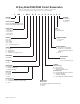
McQuay Model PDAE/PDHE Product Nomenclature Note: For Illustration purposes only. Not all options available with all models. Please consult a McQuay Sales Representative for specific availability.
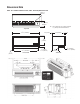
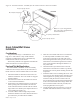
Dimensional Data PDAE – Air Conditioner with Electric Heat / PTHE – Heat Pump with Electric Heat Finished Wall Line 101/2" (267mm) Minimum A = Louver thickness: 3/8" (10mm) stamped, 11/8" (29mm) extruded architectural Top View 447/8" (1140mm) 1/2" (13mm) 20" (508mm) A 163/8" (416mm) 411/2" (1054mm) 11 1 /16" (43mm) Front View 3" (76mm) or 4" (102mm) 61/4" (159mm) 41/4" (108mm) to 133/4" (349mm) Side View IM 950-1 / Page of 38
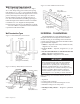
Wall Opening Requirements The rough opening should measure 165/8" high x 451/8" wide. When using a louver frame, the opening must measure 167/8" x 453/8". Louver frames should be used for panel wall and thin wall applications to assure positive anchoring to the wall (Figure 13). When a elecrical subbase is used, the opening must start 3" to 4" above the finished floor (including carpeting) to match the height of the subbase selected.
Electric Service – All wiring should be done in accordance with local and national electrical codes. Electric service for the replacement unit is via a receptacle type outlet furnished with 265V units. 208/230V units are equipped with a plug and cord set to plug into a receptacle which is supplied by others and field installed. The use of an extension cord to increase the length of the plug/cord set furnished as a part of the unit is not recommended. 3.
Preparing Unit for Installation Note: first install the louver frame following steps 1 and 2 as described in "Louver Frame Installation." Remove the outer carton and inspect the conditioner for damage. Report any damage found to the carrier. Note: Save the outer carton for reuse to cover the installed conditioner until ready for use.
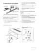
Condensate Drain Kit Installation External Drain Kit Indoor Drain Kit Alternate 6" Long, 1/2" O.D. Straight Copper Tube Figure 10 illustrates the installation of the indoor drain kit. The indoor drain kit must be installed before placing the cabinet/wall sleeve into the opening. Assembly of the external drain kit should be completed after the cabinet/wall sleeve has been installed. Indoor Drain Kit Installation 1.
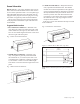
Figure 11. External Drain Kit - installed after the cabinet/wall sleeve has been installed. Neoprene Sponge Gasket Room Side Block off plate and gasket Alternate 6" Long, 1/2" O.D. Straight Copper Tube Steel Mounting Plate Note: Use of 6" straight drain tube will require modification of architectural louver. 1/2" (13mm) O.D. Drain Tube Neoprene Sponge Gasket Room Cabinet/Wall Sleeve Installation Considerations The cabinet/wall sleeve is a standard size 163/8" high, 447/8" wide and 203/4" deep.
Masonry and Thick Wall Applications 1. Preparation of the wall opening — In new construction, the room cabinet/wall sleeve can be built into the building wall as it progresses, or openings can be left for later installation. A lintel by others must be used to support any brick or masonry work above the conditioner. 2. Set the room cabinet/wall sleeve in soft mortar and position it in the wall opening.
Heating/Cooling Chassis Installation 1. Check the chassis for damage. Spin the fan wheels manually to confirm free rotation. Check the refrigerant tubing to determine that there are no kinks and that it does not rub against other parts. Report any shipping damage to the carrier immediately. 2. Check the interior of the installed room cabinet/ wall sleeve. Clean out any dirt or debris that may have accumulated.
Equipment Start-up Initial start-up of any Incremental® conditioner by an experienced technician is usually the responsibility of the installing contractor. This consists of inspecting and operating the equipment for all functions at the time of initial installation and making necessary adjustments. It also includes demonstrating its proper operation to the owner or their agent.
PTAC/PTHP Startup Report – Audit Job Name __________________________________________ City ________________G.O. # ____________ Installer __________________________________________________________________Total No.
Controls (Non-programmable) Standard Digital Touchpad Control Figure 14. Standard Digital Touchpad Control Keys and Indicators Labels 7 Push Buttons ON/OFF, FAN SPEED, MODE FAN MODE, SLEEP for Temp buttons: Temp UP and for Temp DOWN 9 LED Indicators SLEEP, COOL, COOL/DRY, FAN, HEAT, HIGH, LOW, CYCLE, CONT.
Controls Standard Digital Touchpad Control Operation Memory Recall The digital control shall start with the last settings used prior to power down. These settings are saved in a non-volatile memory. Factory set mode is OFF. On/Off Triggering Control can be turned On/Off via LUI, Remote T’stat, or Sleep feature. The control will show the temperature set point when the mode is Cool, Cool Dry, or Heat. The display will be blank in Fan mode. 1.
Controls Standard Digital Touchpad Control System Select Operation Using Remote Thermostat System will run in Heat mode and engage certain outputs based on the system selection (jumper) as described below (see Standard Digital Control Board Wiring Diagram on page 31). AC/ELE • If AC/ELE is selected then a signal on W terminal will call for heating. • If HP or HP/ELE is selected then signals on Y and B terminals will call for heating. HP or HP/ELE NOTES: 1.
Figure 18. Zone C Cool Dry Mode Select the Cool Dry Mode when the standard Cool Mode does not provide sufficient dehumidification. In Cool Dry Mode, the unit must run in Cool Mode for 12 minutes or until the temperature differential between the room temperature and the set point is less than 2°F. This will also occur after a Cold Start or a Mode change from Cool to Cool Dry. During this time the fan will operate in the Mode and Speed selected.
Modes of Operation-Description Standard Digital Touchpad Control Heat Mode Unit will call for heating based on the type of the heat source it has: heat pump in reverse cycle, hydronic or electric. 1) Hot Start Hot Start is possible when the control has not called for heat in more than (2) hours or during poweron-reset. During Hot Start, the user’s set point is raised 4°F (Ts + 4°F). The unit will only call for heat if room temperature differential calls for heat.
Modes of Operation Outdoor Air Sensor Reading To advance from Indoor Coil Sensor reading to Outdoor Air Sensor reading, press the Mode button once. The control readout will show the outdoor air sensor temperature. Figure 21. Outdoor Air Sensor Location Compressor Minimum Off Time (delay on break) When compressor is under the thermostat control, it has a 3-minute delay before restarting when it has cycled off.
Modes of Operation Standard Digital Touchpad Control Temperature Limit Settings 1 To adjust the lower operating temperature limit (cool minimum set point) press and hold Fan Mode button and adjust the setting with Up or Down buttons. The minute setting is 60ºF (15ºC). 2. To adjust the upper operating temperature limit (heat maximum set point) press and hold down Fan Speed button and adjust the setting with Up and Down buttons. The maximum setting is 85ºF (30ºC).
Controls Keys and Indicators Labels 8 Push Buttons ON/OFF, FAN SPEED, MODE, FAN MODE, SLEEP, PROG-ON/OFF for Temp buttons: Temp UP and for Temp DOWN LED with Program Setting Display 9 LED Indicators SLEEP, COOL, COOL/DRY, FAN, HEAT, HIGH, LOW, CYCLE, CONT.
Controls Premium Digital Touchpad Control Clock Set Menu 1.1 To set the time and day of the week, press FAN MODE and FAN SPEED buttons simultaneously for 5 seconds. Time will be displayed first: 2.2 To adjust the lower operating temperature limit and (cool minimum set point) press buttons. COOL and the setting will be displayed as shown below. The minimum and factory default setting is 60°F (15°C). An example of what can be displayed: 2.
Controls Premium Digital Touchpad Control 3.1 The touchpad of the electronic controller can be programmed for four time periods, MORN, DAY, EVE, and NITE that are customizable for each day of the week. Each period will have a start time, heat and cool temperatures. The unit will monitor the day and time, while maintaining the specific conditions for each period of the day. During programming, the item that is flashing is adjustable. 3.
Remote Wall Mounted Thermostats Wall mounted thermostats are available for the PDAE/PDHE unit in automatic or manual changeover styles. All include a fan switch for constant “on” operation or “automatic” for cycle operation with the compressor. When requested, all necessary relays and transformers are factory mounted and ready for attachment to field supplied low voltage wires. All thermostats are 24-volt type and have dual Fahrenheit and Celsius temperature setpoint scales.
Remote Wall Mounted Thermostats Figure 24.
Remote Wall Mounted Thermostats Remote Thermostat Control The Remote Thermostat can be any thermostat that can interface with an electronic thermostat via RCWYBG terminals. The Control Selection jumper must be in T’STAT position. During a call the remote thermostat will pass R back to the controller on a respective terminal. The push buttons on the touchpad become inactive in the remote thermostat mode. However, the control pad LED display will indicate the mode of operation, and the room temperature.
Premium (Programmable) Digital Contol Wiring Diagram 1– Jumper Placement to Select System Module (See Jumper Detail) A– Place jumper across AC/HYD to select Air Conditioner/Hydronic Heat. B– Place jumper across AC/E to select Air Conditioner/Electric Heat. C– Place jumper across AC/HYD/E to select Air Conditioner/Hydronic/Electric. D– Place jumper across HP to select Heat Pump. E– Place jumper across HP/E to select Heat Pump/Electric.
Standard (Non-programmable) Digital Contol Wiring Diagram 1– Jumper Placement to Select System Module (See Jumper Detail) A– Place jumper across AC/E to select Air Conditioner with Electric Heat. B– Place jumper across HP to select Heat Pump. C– Place jumper across HP/E to select Heat Pump with Electric Back-up Heat. 3– Jumper Placement to Select Controller Type: A– Place jumper across LUI to select unit mounted touchpad (Local User Interface).
Wiring Diagrams Digital Control Board With Standby Power The standby power connections, L1 STBY and L2 STBY are meant to run the indoor motor at a separate voltage from the other motors, compressor and outdoor motor. When used as such, the jumpers, JH1 and JH2, must be cut. This renders L1 & L2 and L1 STBY and L2 STBY isolated from each other. If there is no need to run the motors at a separate voltage the L1 = L1 STBY and L2 = L2 STBY. Therefore one voltage is used to run all motors.
Digital Control Board Without Standby Power The standby power connections, L1 STBY and L2 STBY are meant to run the indoor motor at a separate voltage from the other motors, compressor and outdoor motor. When used as such, the jumpers, JH1 and JH2, must be cut. This renders L1 & L2 and L1 STBY and L2 STBY isolated from each other. If there is no need to run the motors at a separate voltage the L1 = L1 STBY and L2 = L2 STBY. Therefore one voltage is used to run all motors.
Maintenance (Scheduled) Incremental conditioners are built to last. With proper care, the unit should provide uninterrupted service for many years. Scheduled maintenance of this equipment as described below, is the key to the equipment’s longevity. A. Air filters must be cleaned at regular intervals. Twice annually may be adequate in some areas while twice monthly may be required in others.
Maintenance An inherent advantage of the Incremental system is that failure of any part affects only one incremental conditioner and does not interrupt the operation of the rest of the system. A further advantage is that a failed part can be quickly and easily replaced, thus minimizing the inoperative time of the equipment. This is so, however, only if a replacement part is quickly available.
Fault and Protection Codes for Applied PTAC/PTHP Control Board Fault code Description Cause for the fault CE Communication Error 1. Cable not plugged in properly on either LUI or relay board. 2. Defective cable. Sh Missing Shunt The user configurable shunt for System Select, Control Select Off Fan Cycle, and/or Hydronic Valve is missing or not placed properly. E1 Problem with IAS Indoor Air Sensor missing or short. E2 Problem with ICS Indoor Coil Sensor missing or short.
Troubleshooting These items should be checked by a qualified service technician only. Trouble 1. 2. Blowers won’t operate on cool Blowers operate on cool but compressor does not start Cause Cure a. No power a. b. c. Faulty touchpad/thermostat. Loose connections at push-button switch. b. c Check supply line fusses, circuit breakers, and be sure the power is on.
Troubleshooting These items should be checked by a qualified service technician only. Trouble 9. Too much cooling. Cause Cure a. b. Thermostat set too low. Defective thermostat a. b. Adjust. Replace. a. Condensate drain from evaporator to condenser plugged. Insulating seals on equipment damaged. Evaporator blower motor not up to speed. Evaporator blower incorrectly positioned. a. Remove obstructions to water flow. b. c. d. b. c. d. Adjust or replace. Check for correct voltage.
Unit Weight - (lbs.) Model PDHE (Packaged) PDAE (Packaged) PDHE (Chassis) PDAE (Chassis) 007 131.0 129.5 116.0 114.5 009 138.5 137.0 123.5 122.0 012 139.4 137.9 124.4 122.9 015 147.1 145.6 132.1 130.6 017 – 145.6 – 130.6 Louvers Flush-stamped................................................6 lbs. (3kg) Architectural..................................................8 lbs. (3kg) Subbase 3" (76mm) High Electrical..........................10 lbs. (5kg). 4" (102mm) High Electrical..................
McQuay Training and Development Now that you have made an investment in modern, efficient McQuay equipment, its care should be a high priority. For training information on all McQuay HVAC products, please visit us at www.mcquay.com and click on training, or call 540-248-9646 and ask for the Training Department. Warranty All McQuay equipment is sold pursuant to its standard terms and conditions of sale, including Limited Product Warranty. Consult your local McQuay Representative for warranty details.