
Operating instructions


IM 950-1 / Page 11 of 38
Masonry and Thick Wall Applications
1. Preparation of the wall opening — In new construc-
tion, the room cabinet/wall sleeve can be built into
the building wall as it progresses, or openings can
be left for later installation.
A
lintel by others must be used to support any brick
or masonry work above the conditioner.
2.
Set the room cabinet/wall sleeve in soft mortar and
position it in the wall opening. The rear face of the
conditioner should be recessed from the outside
edge of the wall opening by the depth of the louver
to be installed. When using the anged stamped
louver, the rear ange of the room cabinet/wall
sleeve will be ush with outside edge of the wall
opening. The center of gravity of the conditioner is
9
1
⁄2" from the rear face. For wall-mounted condi-
tioners, the center of gravity must be within the
load bearing portion of the wall; otherwise, sup-
port is required.
3.
Level the room cabinet/wall sleeve side to side and
pitch down 1/4 bubble to outside. Securely fas-
ten the room cabinet/wall sleeve in the wall from
inside the cabinet through the sides and/or top on
the outdoor side of the weather seal. Make sure
the cabinet is not distorted. Never secure through
the bottom of the cabinet. For installations using
a subbase, level the room cabinet/wall sleeve with
leveling bolts provided with the subbase. Attach
the subbase to the room cabinet/wall sleeve per
instructions provided with the subbase.
4.
After the room cabinet/wall sleeve is installed and
leveled side to side and pitched down 1/4 bubble
to the outside, secure it and the louver frame to the
wall with screws driven through the sides and top
of the room cabinet/wall sleeve outward through
the louver frame. Never secure the frame through
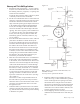
the bottom, as it may cause leaks. A
5
⁄32" diameter
hole has been added to each side of the wall sleeve
as a provision for securing the sleeve in the wall
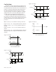
opening. Each hole is located 2" down from the
top and 2" in from the rear of the sleeve. (See Fig-
ures 12 and 13.)
These holes or other non-perforated locations in
the sides and/or top of the sleeve may be used to
fasten the sleeve to the wall from the inside. Never
secure the room cabinet/wall sleeve to the wall
through the bottom.
5.
Caulk the outdoor joint between the room cabinet/
wall sleeve and the wall opening (or louver frame):
top, bottom and both sides. Do not permit caulking
to block the weep holes.
6.
Install the outdoor louver. Holding the louver
with a wire loop, or other similar means, push the
louver out through the rear opening in the room
cabinet/wall sleeve and pull the louver back to
the rear face so that the louver studs pass through
the holes in the room cabinet/wall sleeve ange.
Attach the louver with the washers and nuts, and
securely tighten the louver in place.
7.
Cut the shipping carton as necessary to cover the
installed room cabinet/wall sleeve until ready for
use.
5
⁄32" Dia.
(typical of 2)
Subbase
2"
2"
Figure 14.
Lintel by
others
Louver
Depth
Mortar Base
Outside wall
Note: Subbase is optional on 208/230V units, but
standard on 265V.
Louver frame is optional on all units.
Outside wall
3
3
⁄8"
(86mm)
Louver Depth
Room cabinet/
wall sleeve
Finished Wall
Louver
Frame
Finished Wall
Finished Floor
Optional
Subbase
5
⁄32" Dia.
(typical of 2)
Figure 12.
Finished Floor