
Operating instructions


IM 950-1 / Page 22 of 38
Keys and Indicators Labels
ON/OFF, FAN SPEED, MODE,
8 Push Buttons
F
AN MODE, SLEEP, PROG-ON/OFF
Temp buttons:
for
Temp UP and for Temp DOWN
9 LED Indicators
SLEEP
, COOL, COOL/DRY, FAN,
HEAT, HIGH, LOW, CYCLE, CONT.
LED 2 Digit Displays No Label
Display Function Legend
Tr = Room Temperature
hI = High Room Temperature
Lo = Low Room Temperature
LA = Low Ambient Lockout
rT = Remote Thermostat Control
tP = Touchpad Control
t = Time
Ts = Temperature Setpoint
Rf = Room Freeze Condition
CF = Coil Freeze Protection
F = Fahrenheit
C = Celsius
LC = Control Lockout Mode
Remote Thermostat Control
The Remote Thermostat can be any thermostat
that can interface with an electronic thermostat via
RCWYBG terminals. The Control Selection jumper
must be in T’STAT position. During a call the remote
thermostat will pass R back to the controller on a
respective terminal. The push buttons on the touchpad
become inactive in the remote thermostat mode.
However, the control pad LED display will indicate the
mode of operation, and the room temperature.
Note:
In terms of outputs, there are two types of thermostats:
relay contacts and solid state.
If you open the thermostat and don’t see relays then it
must be solid state.
Manufacturers of solid state output thermostats include
loading resistors on their installation kits. They are
of 560 Ohm and 3W value. These resistors are meant
to load thermostat solid state outputs in order for the
output voltage to be either 0 or 24VAC, i.e. no oating
voltage. These resistors are connected from W, Y, G to
common (C), respectively.
You can wire any type of 24Vac thermostat straight
into the remote thermostat connector of PTAC control
boards, 667997101 and 667997201 (Basic and Pre-
mium models) and the control boards will recognize the
signals from them.
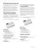
Controls
Premium (Programmable) Digital Touchpad
Control Operating Instructions
LED with
Program
Setting
Display
8- Push
Button
Display
Inputs
9-LED
Indicators
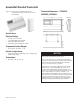
Application
The PTAC Digital Control is used to control
a PTAC Unit that includes both an integral air
conditioner and a source of heat.
The Digital Control is operated with a Touchpad.
Inputs and Outputs
• Indoor coil sensor, (ICS)
• Outdoor coil sensor, (OCS)
• Indoor air sensor, (IAS)
• Outdoor air sensor, (OAS)
• Remote T’stat, T’STAT (RCWYBG)
• Heat Fan Lock Out (HFLO)
• Power supply: (24VAC)
• Line voltage input, (L1, L2)
• Indoor fan standby voltage, (L1STB L2STB)
• Control selection: (LUI, T’STAT
• Model selection: (AC/E, HP, HP/E)
• Time delay bypass, (TEST)
• Indoor off fan cycle: (FAN, OFF CYCLE–10, 20,
30, 1 HR)
Outputs
• Compressor output, COM
• Indoor fan, BLOWER LO, HI
• Outdoor fan, OUTDOOR FAN
• Electric heater, ELE
• Reversing valve, REV VALVE
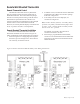
User Interface
The user will by default control the Electronic
Controller via the touchpad. The user can select with
a jumper for the unit to receive commands from a
Remote Thermostat.