Catalog 1301 Applied Packaged Terminal Air Conditioner and Heat Pump Replacement 16" × 44" Flat Top – Models PDAE/PDHE ®
Table of Contents Introduction The Ideal Solution For Replacement................ 4 Unit Features Beyond "Standard" Expectations...................5-6 16" × 44" Flat top Replacement Unit.............7-8 Applied Unit Features Unit Components............................................ 14 Touchpad Controls.....................................10-11 Model Nomenclature............................................ 12 Model Quick Selection Guide............................... 13 ARI Performance Data................
The Ideal Solution for Replacement 450,000 square foot manufacturing plant, located in Auburn, New York Evolution of the 16" × 44" Packaged Terminal Air Conditioners and Heat Pumps: Superior zoned heating and cooling: In 1970, McQuay designed and introduced the first Packaged Terminal Air Conditioner (PTAC) system with an integrated heating and cooling chassis. The 16 × 44 type EA series became a best seller with over 350,000 units sold worldwide.
Beyond “Standard” Expectations Room comfort Manual fresh air damper control - left end Easy to use digital controls The unit control pad offers digital readout and is easy to use when selecting fan speed, mode of operation and temperature setting. A precise digital temperature display provides guests with an exact comfort setting, thereby eliminating uncomfortable temperature swings and costly overheating/overcooling associated with non-digital electromechanical controls.
Beyond “Standard” Expectations Electric heat override Heat pump units can be manually switched to electric heat, providing added freeze protection if the heat pump mode is not available due to a compressor failure.
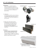
16" × 44" Unit Features 16" × 44" Flat Top – Replacement Unit The right choice for your replacement application Direct replacement for: McQuay/Remington/Singer models, PMES, PMRS, PMEG, EA, RS, MQA (see Replacement Guide, page 5) A. Heating/Cooling chassis Complete air cooled refrigeration system with a low noise tangential fan, outdoor propeller fan with slinger ring provides efficient condensate removal. Fan motors and concealed manual fresh air damper (auto damper for hydronic).
16" × 44" Unit Features C. Combination room cabinet and wall sleeve Constructed of heavy-gauge, zinc-coated phosphatized steel. Antique Ivory powder paint finish provides maximum corrosion protection. Four-position discharge grilles can be easily arranged to provide the proper distribution of air. Through the wall dimension of only 163/8" × 447/8" D. Front Panel Modern styling and ingenious design have resulted in the exclusive, multi-purpose front panel. Four-way room air return around its periphery.
16" × 44" Unit Features H. Fan motors High efficiency, quiet PSC fan motors. All motors are permanently lubricated for extended life. The outdoor fan motor is totally enclosed to help prevent damage from driving rain or excess condensate accumulation in humid climates. H. Indoor fan motor H. Outdoor fan motor I. Compressor The reliable, high efficiency rotary compressor is hermetically sealed and designed for continuous operation.
16" × 44" Unit Features Keys and indicators labels Digital touchpad control The PDAE/PDHE Standard Touchpad Control is used to control both an integral air conditioner and a source of heat. The user will by default control the electronic controller via the touchpad. The user can select with a jumper for the unit to receive commands from a remote thermostat.
16" × 44" Unit Features Premium (7-day programmable) digital touchpad • Provides all the features of the Standard Controller, plus master/slave, infra-red control, auto damper, wall mounted remote thermostat, heat fan lockout Wireless remote control (optional) Note: Only available on select models.
McQuay Model PDAE/PDHE Product Nomenclature Note: For Illustration purposes only. Not all options available with all models. Please consult a McQuay Sales Representative for specific availability.
Model PDAC/PDHP Quick Selection Guide Chassis Customization Options Description Unit Size Unit Type - PDAE/PDHE 007 009 012 Cabinet Type 16 × 44 Top Mount Hydronic 16 × 44 Flat Top Replacement Unit 115/60/1 Voltage 208/230/60/1 265/277/60/1 208/230-60/1 w/ standby 115/60/1 • • • • • • Cooling Capacity BTUH 7,900 • • • • • • 10,500 015 017 • • • • • • • • • • • 12,800 • • • • 14,800 17,000 Heating Options 2.5 Electric Heater (kW) 3.
ARI Performance Data (6) UNIT SIZE Cooling 007 015 017 7,900 7,900 10,200 10,200 10,200 12,800 12,800 12,800 14,800 14,800 16,600 Sensible Btuh(1) 6,800 6,800 6,800 7,900 7,900 7,900 8,900 8,900 8,900 9,600 9,600 12,000 EER 12.10 12.10 12.10 11.60 11.60 11.60 11.20 11.20 11.20 10.10 10.10 9.40 Volts 115 208/230 265 115 208/230 265 115 208/230 265 208/230 265 208/230 Full Load Amps(5) 7.03 3.39 3.04 8.83 4.49 4.04 11.86 5.83 5.19 7.43 6.
Dimensional Data – 16" × 44" Replacement Unit PDAE – Air Conditioner with Electric Heat / PDHE – Heat Pump with Electric Heat Finished Wall Line 101/2" (267mm) Minimum A = Louver thickness: 3/8" (10mm) stamped, 11/8" (29mm) extruded architectural Top View 447/8" (1140mm) 1/2" (13mm) 20" (508mm) A 163/8" (416mm) 411/2" (1054mm) 111/16" (43mm) Front View 3" (76mm) or 4" (102mm) 61/4" (159mm) 41/4" (108mm) to 133/4" (349mm) Side View Catalog 1301 / Page 15 of 32
Typical Installation – 16" × 44" Replacement Unit The 16" × 44" PDAE/PDHE conditioner can be mounted flat on the floor for the lowest possible silhouette, off the floor at any convenient height, or on an optional universal telescopic subbase which adjusts to any wall thickness. Typical room cabinet and wall sleeve Finished Wall Room Cabinet/Wall Sleeve 33/8" (86mm) A Louver Depth Subbase Louver Frame Finished Floor Outside Wall 2" 2" Finished Wall B 1/2" (13mm) 101/2" (267mm) Min.
Accessories Wall mounted thermostats – quick selection guide Thermostat Item Number 107095701 107095801 107095901 • • • • • • • • • • • • • Single Stage Two Stage Heat Pump Manual Changeover (Cool/Off/Heat) • • • • Settable Differential Range Auto Changeover Status LEDs Backlit Display 7-Day Programmable Temporary and Vacation Hold • • • Programmable Fan On/Off Delay Non-Programmable Hard Wired • • • • • • • • • Wireless 4 or 5 Wire Capable Freeze Protection Fan S
Accessories Wall mounted, non-programmable thermostat Wall mounted, 7-day programmable thermostat Manual changeover one-stage heat and cool or one-stage heat pump Manual changeover one-stage heat and cool or one-stage heat pump McQuay Part No.
Accessories Wall mounted, 7-day programmable thermostat Optional remote sensor - Part No. 667720401 Standard auto or manual changeover two stage heat / two stage cool McQuay Part No. 107095901 (1-Pk, White with Wall Plate) The fast, easy solution for temperature sensing problems.
Accessories Subbase – Weight 3" (76mm) High Electrical........................... 10 lbs. (5kg). 4" (102mm) High Electrical....................... 12 lbs. (5.4kg) Electrical Junction Box for Main Power Connection Electrical subbase 3" or 4" high 3" × 5" Opening for Electrical and/or Drain Rough-In An electric subbase is available for the PDAE/ PDHE unit. The subbase height can be either 3" or 4". Leveling legs are supplied with the subbase which allow for an additional 1" adjustment.
Accessories Drain Kits Drain kits are recommended for the heat pump units, and may be used on any unit as required. They eliminate excessive condensate accumulation which is generated during the heating cycle of the heat pump. There are two types of drain kits employed with the Packaged Terminal equipment; internal drains and external drains. Internal Drain An internal drain is mounted to the bottom of the wall sleeve prior to installation of the sleeve.
Accessories Wall Sleeve Extension Table 2. Maximum Wall Thickness without Sleeve Extensions PDAE/PDHE 16" × 44" Replacement Unit The standard wall sleeve will accommodate the maximum wall thickness described in Table 2. For thicker walls, wall sleeve extensions are available from your local distributor. Air splitters will be included in the wall sleeve extension as shown in the illustrations below.
Accessories Architectural louver Louvers Attractive, rugged architectural louvers are extruded aluminum and are finished natural and clear anodized (optional colors are also available). Louvers by others are acceptable as long as they meet factory specifications. They must have a minimum free area of 70% or a pressure drop not exceeding .05 in. w.g. at 300 fpm face velocity, and a blade design that will not cause recirculation of condenser air.
Wiring Diagrams Premium (Programmable) Digital Control 1– Jumper Placement to Select System Module (See Jumper Detail) A– Place jumper across AC/HYD to select Air Conditioner/Hydronic Heat. B– Place jumper across AC/E to select Air Conditioner/Electric Heat. C– Place jumper across AC/HYD/E to select Air Conditioner/Hydronic/Electric. D– Place jumper across HP to select Heat Pump E– P l a c e j u m p e r a c r o s s H P / E t o s e l e c t Heat Pump/Electric.
Wiring Diagrams Standard (Non-Programmable) Digital Control 1– Jumper Placement to Select System Module (See Jumper Detail) A– Place jumper across AC/E to select Air Conditioner with Electric Heat. B– Place jumper across HP to select Heat Pump C– Place jumper across HP/E to select Heat Pump with Electric Back-up Heat.
Wiring Diagrams Digital Control Board With Standby Power The standby power connections, L1 STBY and L2 STBY are meant to run the indoor motor at a separate voltage from the other motors, compressor and outdoor motor. When used as such, the jumpers, JH1 and JH2, must be cut. This renders L1 & L2 and L1 STBY and L2 STBY isolated from each other. If there is no need to run the motors at a separate voltage the L1 = L1 STBY and L2 = L2 STBY. Therefore one voltage is used to run all motors.
Wiring Diagrams Digital Control Board Without Standby Power The standby power connections, L1 STBY and L2 STBY are meant to run the indoor motor at a separate voltage from the other motors, compressor and outdoor motor. When used as such, the jumpers, JH1 and JH2, must be cut. This renders L1 & L2 and L1 STBY and L2 STBY isolated from each other. If there is no need to run the motors at a separate voltage the L1 = L1 STBY and L2 = L2 STBY. Therefore one voltage is used to run all motors.
Engineering Guide Specifications – 16" × 44" Flat Top Configuration Furnish and install where shown on plans (packaged terminal air conditioners) (packaged terminal heat pumps) of the sizes and capacities shown on the schedule. The units shall be located as shown on the drawings and shall include cabinet/wall sleeve, chassis, outdoor louver, and room cabinet. (Units furnished with hydronic heat shall also include a hydronic subbase, valve and appropriate controls).
Engineering Guide Specifications – 16" × 44" Flat Top Configuration Hydronic Heat - Heat Fan Lock Out – When the control is in the heat mode and calling for heat, the indoor fan shall not turn on until the HFLO sensor is above 115°F. If at any time while the unit is in heat mode the HFLO sensor is below 95°F, the indoor fan shall turn off immediately. Control will check if the HFLO sensor temperature is above 115°F for 2 seconds before resuming indoor fan operation.
Engineering Guide Specifications – 16" × 44" Flat Top Configuration Inputs and outputs The PDAC/HP control module offers the following inputs: 1. 2. 3. 4. 5. 6. Indoor Coil Sensor (ICS) Indoor Air Sensor (IAS) Outdoor Air Sensor (OAS) Inputs from Remote Thermostat (R, B, G, Y, W) Heat Fan Lock Out Sensor (HFLO) Power Supply, 24VAC The PDAC/HP control module offers the following outputs: 1. Compressor Output (COM) 2. Outdoor Fan (FAN) 3.
Engineering Guide Specifications – 16" × 44" Flat Top Configuration Filtration (Standard) – Room side return air shall be completely filtered through a permanent, washable polypropylene mesh filter. Foam type filters are not acceptable. Filter must be a UL listed class II, 38% average arrestance efficiency (ASHRAE test) air filter with low resistance to airflow (0.02 w.g. at 300 CFM) and high dust holding capacity of 55 grams.
Warranty All McQuay equipment is sold pursuant to its standard terms and conditions of sale, including Limited Product Warranty. Consult your local McQuay Representative for warranty details. Refer to Form 933-43285Y. To find your local McQuay Representative, go to www.mcquay.com. This document contains the most current product information as of this printing. For the most up-to-date product information, please go to www.mcquay.com. ® © 2008 McQuay International • www.mcquay.