
Specifications


Catalog 1301 / Page 22 of 32
Accessories
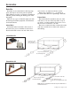
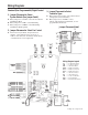
Dimension 16" × 44" Replacement Unit
A 11
7
/8"
B 25"
C 7
5
/8"
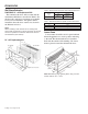
Wall Sleeve Extension
PDAE/PDHE 16" × 44" Replacement Unit
The standard wall sleeve will accommodate the
maximum wall thickness described in Table 2. For
thicker walls, wall sleeve extensions are available
from your local distributor. Air splitters will be
included in the wall sleeve extension as shown in
the illustrations below.
Note:
When installing a new chassis into an existing wall
sleeve with an extension, it will be necessary to relocate
the two air splitters to match the dimensions shown in
the illustrations (see Table 3).
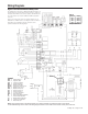
Table 2. Maximum Wall Thickness without Sleeve Extensions
Maximum Wall Thickness
Louver
No Standard
Type
Subbase Subbase
Architectural 1
1
/8" 14
7
/8" 10
3
/8"
42
3
/16"
(1072mm)
16
3
/16"
(411mm)
3
3
/4"
(92mm)
44
3
/16"
(1122mm)
18
3
/16"
(1072mm)
Note: Wall Sleeve rough opening when using a Louver
Frame must be 16
5
/8" × 42
5
/8"
Louver Frame
Louver frames should be used for panel wall and
thin wall applications to assure positive anchoring
to the wall. The cabinet/wall sleeve is installed
ush with the outside of the building. The louver
frame is placed around the cabinet/wall sleeve.
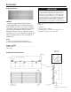
Wall Sleeve Extension
Room Side
B
16"
B
A
C
44.5"
Air Splitters
16" × 44" Replacement Unit
Table 3. Wall Sleeve Extension Splitter Location Dimensions
as required