
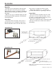
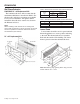
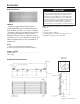
Specifications


Catalog 1301 / Page 27 of 32
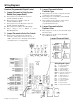
Wiring Diagrams
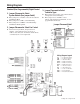
Digital Control Board Without Standby Power
Legend
DM = Damper Motor
HYV = Hydronic Valve
CM = Compressor Motor
IFM = Indoor Fan Motor
OFM = Outdoor Fan Motor
HFLO = Heat Fan Lockout Sensor
OCS = Outdoor Coil Sensor
OAS = Outdoor Air Sensor
ICS = Indoor Coil Sensor
IAS = Indoor Air Sensor
LUI = Local User Interface
REV = Reversing Valve
IR = IR Receiver Board (AP7810)
C1 = Indoor Motor Capacitor
C2 = Outdoor Motor Capacitor
C3 = Compressor Capacitor
MP = Motor Protector
Note: The gray tinted areas in the wiring diagram; are options available only with the premium control board.
For the latest drawing version refer to the wiring diagram located on the inside of the controls access panel of the unit.
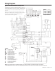
Wire Color Voltage
WH 120V
RD 208V
OR 240V
BN 277V
Drawing No. 668001406
Table A
The standby power connections, L1 STBY and L2 STBY are meant to run
the indoor motor at a separate voltage from the other motors, compressor
and outdoor motor. When used as such, the jumpers, JH1 and JH2, must
be cut. This renders L1 & L2 and L1 STBY and L2 STBY isolated from
each other.
If there is no need to run the motors at a separate voltage the L1 = L1
STBY and L2 = L2 STBY. Therefore one voltage is used to run all motors.
If the jumpers are accidentally cut, then the connections can be
spliced to substitute for the missing jumpers.