Installation & Maintenance Data IM 934 Group: PTAC Part Number: 668966801 Date: December 2008 Applied Packaged Terminal Air Conditioner and Heat Pump Model PDAA & PDHA Dual Motor Angled Top Unit - 16" x 42" ® ©2008 McQuay International
Table of Contents Safety Information........................................................3 Inspection......................................................................3 Nomenclature................................................................4 Introduction...................................................................5 Dimensional Data........................................................6 Wall Opening Requirements...................................7 Wall Construction Types..................
Safety Information Follow all safety codes. Wear safety glasses and work gloves. Use a quenching cloth for brazing operations. Have a fire extinguisher available. Follow all warnings and cautions in these instructions and attached to the unit. Consult applicable local building codes and National Electrical Codes (NEC) for special requirements. Recognize safety information. When you see a safety symbol on the unit or in these instructions, be alert to the potential for personal injury.
McQuay Model PDAA/PDHA Product Nomenclature Note: For Illustration purposes only. Not all options available with all models. Please consult a McQuay Sales Representative for specific availability.
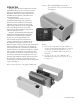
Introduction McQuay offers the most complete line of PTAC and PTHP products for new construction projects and exact replacements for our original Singer, Remington, American Air Filter and American Standard brand equipment, and models from other manufacturers. McQuay products feature our proven institutional grade design and construction that allows you to benefit from the long life, reliability, and low sound levels, along with higher energy efficiencies for lower operating costs.
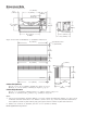
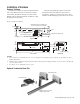
Dimensional Data Figure 3. Chassis Dimensions 42" (1067mm) 523/32" (145mm) 24" (610mm) 101/32" (255mm) 1/2" (13mm) Flange Type 1929/32" (506mm) 1719/64" (439mm) Base Pan 141/2" (368mm) 175/16" (440mm) 285/8" (727mm) Fin Width 1929/32" (506mm) Figure 4.
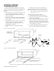
Wall Opening Requirements When roughing in the opening for the wall sleeve, make certain there is sufficient clearance from the walls and floor. The wall sleeve should be positioned a minimum of 5/8" in from the room side finished wall to accommodate the room cabinet. A minimum distance of 3" above the finished floor is required for return air. The rough opening should measure 161/4" high x 1 42 /4" wide. When using a louver frame, the opening must measure 165/8" x 425/8".
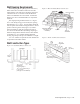
Installation of Subbase Electric Subbase 3. Insert leveling bolts into subbase bottom flange. Four (4) bolts will be needed if side extensions are used. Only two (2) bolts are required if side extensions are not used. 4. Place the subbase on the floor and align its center line with the center line of the wall opening. Do not fasten the subbase to the floor. Attach the subbase to the wall sleeve using the clips provided with the subbase. 5.
Installation of Subbase Hydronic Subbase A subbase is available as required with all hydronic units. This subbase measures 8" (203mm) in height and includes the hydronic heating coil. Refer to IM Bulletin 936 for installation details. In addition, rough in supply and return piping. Electrical and plumbing rough-in can be done through the back of the hydronic heat section or through the openings provided in the bottom of the subbase. The finished piping can be done now or later. Figure 9.
Installation of Optional Condensate Drain Kit Figure 10 illustrates the installation of the indoor drain kit. The indoor drain kit must be installed before placing the wall sleeve into the opening. Install as follows: 1. Locate the drain so that it will be on the room side of the wall when the wall sleeve is installed. 2. Drill a 1/2" diameter hole in the base of the wall sleeve for the drain. 3. Drill two (2) 5/32" pilot holes for the mounting screws.
Installation of Wall Sleeve Figure 12. Wall Sleeve Extension Considerations 24" The wall sleeve is a standard size 16" high, 42" wide and 133/4" deep. Slide channels are factory welded into the sleeve to facilitate easy installation and removal of the chassis. Each wall sleeve is predrilled to match the mounting screws of the chassis. Knockouts are provided for the optional external drain kit used with the heat pump models.
Installation of Recessed Louver Wall Sleeve Figure 14.
Installation of Basic Wall Sleeve Anchoring The Wall Sleeve Anchoring the wall sleeve in the opening is accomplished as shown in figure 15. CAUTION DO NOT drill holes in the bottom of the wall sleeve as it will cause leaks. It is recommended that rubber isolation washers be used with the fasteners to minimize sound transmission from the equipment to the wall at the point of contact. Figure 15.
Installation of Basic Wall Sleeve Figure 16. Frame and brick with electrical subbase Figure 18.
Installation of Basic Wall Sleeve 5. Recess the wall sleeve so that the louver is flush with the exterior of the building. 6. Level wall sleeve in both directions and secure by anchoring with appropriate fasteners or drill additional holes as required to secure firmly. Refer to Anchoring The Wall Sleeve instructions on page 13. 3. Secure the two sections by installing the clip screws supplied with the hardware bag. 4. Caulk indoor/outdoor perimeter of wall sleeve with resilient caulk such as silicone. 5.
Installation of Basic Wall Sleeve Thick Wall Construction Type Installation of wall sleeves for thick walls requires special consideration. Table 2 should be used to determine the maximum wall thickness allowed for the basic wall sleeve. For thicker walls, wall sleeve exten sions are available from your representative (see page 11 for details). Wall sleeve installation in thick walls is similar to frame and brick installation. Install as follows (Figure 22, 23, & 24). 1.
Installation of Basic Wall Sleeve Figure 24. Thick wall installation with hydronic subbase Figure 25. Flush Stamped Louver See Table 2, page 16 Steel Lintel (by others) Caulk Perimeter 1" (25mm) Wall Sleeve 133/4" (349mm) Mounting Screws (by installer) Outside Louver 16" (406mm) Wall Sleeve Extension Room Cabinet 81/4" (209mm) Figure 26. Architectural Louver 17" (432mm) Hydronic Heating Coil 81/4" (209mm) Floor Hydronic Subbase Attaching Wall Sleeve to Subbase 1.
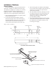
Typical Louver Design Figure 27 illustrates some typical louver designs. The “X” dimension represents the narrowest dimension through which air must pass. The “Y” dimension represents the increment of rise between the blades. To calculate the percentage of free area, divide dimension “X” by dimension “Y” (see Example). Installation of Louver 1 2 3. Figure 27. Louver Designs 4. 5. 6. Remove louver and mounting hardware from the shipping carton. Remove temporary cardboard weather panel from wall sleeve.
6. If wall sleeve has been previously installed, remove temporary cardboard weather panel. 7 If louver has been previously installed, remove temporary cardboard weather panel. 8 Place Tinnerman clips on wall sleeve. Clips and mounting screws enclosed in a bag attached to the inside chassis side panel (Figure 28). 9. Rotate fans to be sure they are free of obstruction. 10. Check all fasteners to make certain they did not loosen during shipment.
Controls (Non-programmable) Figure 30. Standard Digital Control Indicators Standard Digital Touchpad Control LED 2-Digit Display Figure 29. Standard Digital Touchpad Control 9- LED Indicators 7- Push Buttons User Interface Application The PTAC Digital Control is used to control a PTAC Unit that includes both an integral air conditioner and a source of heat. The Digital Control is operated with a Touchpad.
Controls Standard Digital Touchpad Control Operation Memory Recall The digital control shall start with the last settings used prior to power down. These settings are saved in a non-volatile memory. Factory set mode is OFF. On/Off Triggering Control can be turned On/Off via LUI, Remote T’stat, or Sleep feature. The control will show the temperature set point when the mode is Cool, Cool Dry, or Heat. The display will be blank in Fan mode. 1.
Controls Standard Digital Touchpad Control System Select Operation Using Remote Thermostat System will run in Heat mode and engage certain outputs based on the system selection (jumper) as described below (see Standard Digital Control Board Wiring Diagram on page 34). AC/ELE • If AC/ELE is selected then a signal on W terminal will call for heating. • If HP or HP/ELE is selected then signals on Y and B terminals will call for heating. HP or HP/ELE Notes: 1.
Cool Dry Mode Figure 33. Zone C Select the Cool Dry Mode when the standard Cool Mode does not provide sufficient dehumidification. In Cool Dry Mode, the unit must run in Cool Mode for 12 minutes or until the temperature differential between the room temperature and the set point is less than 2°F. This will also occur after a Cold Start or a Mode change from Cool to Cool Dry. During this time, the fan will operate in the Mode and Speed selected.
PRELIMINARY Modes of Operation-Description Standard Digital Touchpad Control Heat Mode Unit will call for heating based on the type of the heat source it has: heat pump in reverse cycle or electric. 1) Hot Start: Hot Start is possible when the control has not called for heat in more than (2) hours or during poweron-reset. During Hot Start, the user’s set point is raised 4°F (Ts + 4°F). The unit will only call for heat if room temperature differential calls for heat.
Modes of Operation Standard Digital Touchpad Control Outdoor Air Sensor Reading To advance from Indoor Coil Sensor reading to Outdoor Air Sensor reading, press the Mode button once. The control readout will show the outdoor air sensor temperature. Figure 36. Outdoor Air Sensor Location Outdoor Air Sensor (OAS) Thermistor Failure Code and Condition The system treats a sensor open or short as extremely cold or hot and reacts accordingly.
Modes of Operation Standard Digital Touchpad Control Temperature Limit Settings 1 To adjust the lower operating temperature limit (cool minimum set point) press and hold Fan Mode button and adjust the setting with Up or Down buttons. The minute setting is 60ºF (15ºC). 2. To adjust the upper operating temperature limit (heat maximum set point) press and hold down Fan Speed button and adjust the setting with Up and Down buttons. The maximum setting is 85ºF (30ºC).
PTAC/PTHP Startup Report – Audit Job Name __________________________________________ City ________________G.O. # ____________ Installer __________________________________________________________________Total No.
Controls Premium (Programmable) Digital Touchpad Control Operating Instructions LED with Program Setting Display 9-LED Indicators Application The PTAC Digital Control is used to control a PTAC Unit that includes both an integral air conditioner and a source of heat. The Digital Control is operated with a Touchpad.
Controls Premium Digital Touchpad Control Clock Set Menu 1.1 To set the time and day of the week, press FAN MODE and FAN SPEED buttons simultaneously for 5 seconds. Time will be displayed first: 2.2 To adjust the lower operating temperature limit (cool minimum set point) press and buttons. COOL and the setting will be displayed as shown below. The minimum and factory default setting is 60°F (15°C). An example of what can be displayed: 2.
Controls Premium Digital Touchpad Control 3.1 The touchpad of the electronic controller can be programmed for four time periods, MORN, DAY, EVE, and NITE that are customizable for each day of the week. Each period will have a start time, heat and cool temperatures. The unit will monitor the day and time, while maintaining the specific conditions for each period of the day. During programming, the item that is flashing is adjustable. 3.
Controls Remote Wall Mounted Thermostats Wall mounted thermostats are available for the PDAA/PDHA unit in automatic or manual changeover styles. All include a fan switch for constant “on” operation or “automatic” for cycle operation with the compressor. When requested, all necessary relays and transformers are factory mounted and ready for attachment to field supplied low voltage wires. All thermostats are 24-volt type and have dual Fahrenheit and Celsius temperature setpoint scales.
Controls Remote Wall Mounted Thermostats Figure 39.
Remote Wall Mounted Thermostats Remote Thermostat Control The Remote Thermostat can be any thermostat that can interface with an electronic thermostat via RCWYBG terminals. The Control Selection jumper must be in T’STAT position. During a call the remote thermostat will pass R back to the controller on a respective terminal. The push buttons on the touchpad become inactive in the remote thermostat mode. However, the control pad LED display will indicate the mode of operation, and the room temperature.
Premium (Programmable) Digital Contol Wiring Diagram 1– Jumper Placement to Select System Module (See Jumper Detail) A– Place jumper across AC/HYD to select Air Conditioner/Hydronic Heat. B– Place jumper across AC/E to select Air Conditioner/Electric Heat. C– Place jumper across AC/HYD/E to select Air Conditioner/Hydronic/Electric. D– Place jumper across HP to select Heat Pump. E– Place jumper across HP/E to select Heat Pump/Electric.
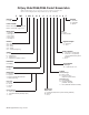
Standard (Non-programmable) Digital Contol Wiring Diagram 1– Jumper Placement to Select System Module (See Jumper Detail) A– Place jumper across AC/E to select Air Conditioner with Electric Heat. B– Place jumper across HP to select Heat Pump. C– Place jumper across HP/E to select Heat Pump with Electric Back-up Heat. 3– Jumper Placement to Select Controller Type: A– Place jumper across LUI to select unit mounted touchpad (Local User Interface).
Wiring Diagrams Digital Control Board With Standby Power The standby power connections, L1 STBY and L2 STBY are meant to run the indoor motor at a separate voltage from the other motors, compressor and outdoor motor. When used as such, the jumpers, JH1 and JH2, must be cut. This renders L1 & L2 and L1 STBY and L2 STBY isolated from each other. If there is no need to run the motors at a separate voltage the L1 = L1 STBY and L2 = L2 STBY. Therefore one voltage is used to run all motors.
Digital Control Board Without Standby Power The standby power connections, L1 STBY and L2 STBY are meant to run the indoor motor at a separate voltage from the other motors, compressor and outdoor motor. When used as such, the jumpers, JH1 and JH2, must be cut. This renders L1 & L2 and L1 STBY and L2 STBY isolated from each other. If there is no need to run the motors at a separate voltage the L1 = L1 STBY and L2 = L2 STBY. Therefore one voltage is used to run all motors.
Maintenance (Scheduled) Incremental conditioners are built to last. With proper care, the unit should provide uninterrupted service for many years. Scheduled maintenance of this equipment as described below is the key to the equipment’s longevity. A. Air filters must be cleaned at regular intervals. Twice annually may be adequate in some areas while twice monthly may be required in others.
Maintenance An inherent advantage of the Incremental system is that failure of any part affects only one incremental conditioner and does not interrupt the operation of the rest of the system. A further advantage is that a failed part can be quickly and easily replaced, thus minimizing the inoperative time of the equipment. This is so, however, only if a replacement part is quickly available.
Fault and Protection Codes for Applied PTAC/PTHP Control Board Fault code Description Cause for the fault CE Communication Error 1. Cable not plugged in properly on either LUI or relay board. 2. Defective cable. Sh Missing Shunt The user configurable shunt for System Select, Control Select Off Fan Cycle, and/or Hydronic Valve is missing or not placed properly. E1 Problem with IAS Indoor Air Sensor missing or short. E2 Problem with ICS Indoor Coil Sensor missing or short.
Troubleshooting These items should be checked by a qualified service technician only. Trouble 1. 2. Blowers won’t operate on cool Blowers operate on cool but compressor does not start Cause Cure a. No power a. b. c. Faulty push-button switch Loose connections at push-button switch b. c Check supply line fusses, circuit breakers, and be sure the power is on.
Troubleshooting These items should be checked by a qualified service technician only. Trouble 9. Too much cooling. Cause Cure a. b. Thermostat set too low. Defective thermostat a. b. Adjust. Replace. a. a. Remove obstructions to water flow. b. c. d. Condensate drain from evaporator to condenser plugged. Insulating seals on equipment damaged. Evaporator blower motor not up to speed. Evaporator blower incorrectly positioned. b. c. d. Adjust or replace. Check for correct voltage.
Unit Weight - (lbs.) Model PDHA (Packaged) PDAA (Packaged) PDHA (Chassis) PDAA (Chassis) 007 146.0 144.5 131.0 129.5 009 153.5 152.0 138.5 137.0 012 154.4 152.9 139.4 137.9 015 162.1 160.6 147.1 145.6 017 – 165.6 – 150.6 Louvers Flush-stamped................................................6 lbs. (3kg) Architectural..................................................8 lbs. (3kg) Subbase 3" (76mm) High Electrical..........................10 lbs. (5kg). 4" (102mm) High Electrical..................
McQuay Training and Development Now that you have made an investment in modern, efficient McQuay equipment, its care should be a high priority. For training information on all McQuay HVAC products, please visit us at www.mcquay.com and click on training, or call 540-248-9646 and ask for the Training Department. Warranty All McQuay equipment is sold pursuant to its standard terms and conditions of sale, including Limited Product Warranty. Consult your local McQuay Representative for warranty details.