INSTALLATION MANUAL IM-5ACC-0205SC Group: Mini Chiller Part Number: A08019024588 Date: February 2005 AIR COOLED CHILLER (R410A SINGLE COMPRESSOR SERIES) © 2005 McQuay International
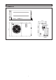
OUTLINE AND DIMENSIONS 80,0 300,0 80,0 English 5AC 020/025 CR 10,0 1181,6 10,0 460,0 128,5 55,2 475,0 789,5 85,0 128,5 i
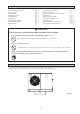
! Caution Sharp edges and coil surfaces are potential locations which may cause injury hazards. Avoid from being in contact with these places. ! Avertissement Les bords coupants et les surfaces du refroidisseur tuulaire présentent un risque de blessure. Mieux vaut éviter le contact avec ces endroits. ! Vorsicht Scharfe Kanten und Wärmetauscherflächen stellen eine Gefahrenquelle dar. Jeglicher Kontakt mit diesen Stellen ist zu vermeiden.
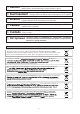
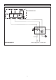
W_PUMP AUX-H BOILER COM1 COM2 LIVE iii 220-240/1pH/50Hz TB1 L/L1 N/L2 ALM_OUT ALM_IN A_FREEZE 4WV1 OUT_FAN1 LP 1 FL OFF HEAT COOL 4WV H T R AL AL IN OUT ENTERING WATER SENSOR LEAVING WATER SENSOR OUTDOOR AIR TEMP SENSOR COMP DISCHARGE SENSOR (1) DEFROST SENSOR (1) O/F C/H 4WV PUMP HTR HP ON 2 WI WO OA CD1 CD2 DF1 DF2 4WV2 TB2 12V 12V 12V N1 N1 N1 12V F02 F01 LP2 LP1 HP2 HP1 C02 C01 FLOW PO ALM DE2 DE1 C/H ON/OFF OUT_FAN2 CN6 TB3 OF IN OF OUT 95 98 COMP 96 E COMP.
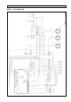
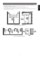
ISOLATOR DIAGRAM AC TERMINAL BOX TB1 L/L1 N/L2 E ISOLATOR FUSE L1 N Power supply 230V / 1Ph-N / 50Hz 5AC/AC020/025 CR iv
English INSTALLATION MANUAL This manual provides the procedures of installation to ensure a safe and good standard of operation for the chiller. Special adjustments may be necessary to suit local requirements. Before using the chiller, please read this instruction manual carefully and keep it for future reference.
INDEX - Outline And Dimensions - Electrical Wiring Diagram - Isolator Diagram - Transportation - Installation Location - Unit Installation - Physical Data - Water Piping and Fitting - Electrical And Wiring - Electrical Data page page page page page page page page page page i-ii iii iv 1 2 3 4 5 5 5 - Recommended Fuse And Cable Sizes - Water Piping System Setup - Refrigerant Circuit - Special Precautions When Dealing With R410A Unit - Control Operation Guide - Servicing And Maintenance - Troubleshooting -
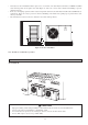
MIN 500 500 500 AIR FLOW 1500 AIR FLOW 500 Figure 2: For single unit installation 500 1000 1000 500 AIR FLOW AIR FLOW AIR FLOW AIR FLOW 1500 • • • Installation work should be done by the authorized dealer or qualified contractor. Never install the unit yourself. Make sure there is sufficient space for airflow around the unit. The discharged air should be directed outside using a duct should the unit be installed in a plant room.
• • • Unit subjects to floor installation must be placed on a concrete slab. The slab must have thickness of 100mm and 50mm wider and longer than the footprint of the unit (Figure 4). Place the concrete slab a distant from building to prevent vibration and noise. In the case of heatpump operation with an outdoor temperature below 0°C, the unit must be installed at least 300mm above ground level.
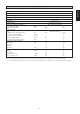
PHYSICAL DATA Model 5AC020CR 5AC025CR 4.98 6.15 Nominal cooling capacity kW Nominal heating capacity kW 6.30 7.320 Operating Weight kg 115.50 122.50 Refrigerant charge R410A kg 1.20 Compressor 1.
WATER PIPING AND FITTING • • • • • • • • • All water pipe must be adequately insulated to prevent capacity losses and condensation. Install a 40 to 60-mesh strainer to ensure good water quality. Water pipes recommended are black steel pipe and copper pipe. During installation, the piping of the unit should be clamped before rotating the installation pipe to reduce the moment induce on the piping. Users are recommended to install the pipes and accessories as shown in Figure 5.
RECOMMENDED FUSE AND CABLE SIZES Cooling / Heat Pump Model 5AC020CR 220 ~ 240V /1Ph /50Hz + N + ! 27 38 10 10 3 3 1.5 1.5 A mm2 mm2 English Voltage Range ** Recommended Fuse * Power Supply Cable Size * Number of Conductor Interconnection Cable Size * 5AC025CR IMPORTANT : * The figures shown in the table are for information purpose only. They should be checked and selected to comply with the local/national codes of regulations. This is also subjected to the type of installation and conductors used.
WATER PIPING SYSTEM SETUP • • • Fill up the water circuit after connecting all the pipes and equipment. Perform leak checks for all connections and joints. Do not start the unit when the system is leaking. To optimize the capacity of the system, ensure that the system is free of air bubbles. The air trapped in the system would make the system unbalanced. Ensure that the water tank is not full. This is to ensure optimal performance of the mini chiller.
The unit is equipped with a microprocessor controller board. The microprocessor controller is provided to give temperature control for the system by accurately measuring and controlling the water entering and water leaving temperature. The temperature setting in the unit is preset in the factory. It is not recommended to change the setting unless necessary. A wired controller handset is connected to the microprocessor board. Every parameter setting and reading can be observed from the LCD of the handset.
SERVICING AND MAINTENANCE • Servicing Servicing or maintenance of these units must be carried out by experienced personnel with specific training in refrigeration. Repeatedly check the safety devices and continuous cycling of control components. These items must be analyzed and corrected before being reset. The simple design of the refrigeration circuit totally eliminates potential problems during normal unit operation.
TROUBLESHOOTING SYMPTOMS POSSIBLE CAUSES 1. Compressor does not start. • No power supply. • Fuses blown or automatic circuit breakdown open. • Defective contactor or coil. • Unit is stopped because safety device has tripped. • Loose wires. REMEDIAL ACTION • Check power supply. • Look for short circuit or grounded wires in motor windings. Replace fuses and reset circuit breakers when the fault has been corrected. Check tightness and soundness of all electrical connections. • Repair or replace.
FAN SPEED CONTROLLER (OPTIONAL) Operation of the mini chillers without any fan speed control is limited to an ambient temperature of 17°C. With the fan speed control, the units are able to operate down to -5°C. The fan speed controller does not come as a standard item in the mini chiller units. It is fieldinstalled. All mini chillers will have a 1/4" access valve provided for along the liquid line of the refrigerant circuit. This valve is for direct pressure connection to the fan speed controller.
• In the event that there is any conflict in the interpretation of this manual and any translation of the same in any language, the English version of this manual shall prevail. • The manufacturer reserves the right to revise any of the specification and design contain herein at any time without prior notification. • En cas de désaccord sur l’interprétation de ce manuel ou une de ses traductions, la version anglaise fera autorité.