
Installation manual


IM-487 Page 17
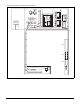
Assembly Instructions:
1. Set curbing parts A thru H per dimensions shown over roof opening or on a level surface. Note location of return and supply air openings.
2. If applicable, set other curbing parts (D, L, M, etc.) in place making sure that the orientation agrees with the assembly instructions.
Check alignment of all mating bolt holes. See Detail "A".
3. Bolt curbing parts together using fasteners provided. Tighten all bolts finger tight.
4. Square entire curbing assembly and securely tighten all bolts.
5. Position curb assembly over roof openings. Curb must be level from side to side and over its length.
Check that top surface of the curb is flat with no bowing or sagging.
6. Weld curbing in place. Caulk all seams watertight. Remove backing from 0.25 thick x 1.50 wide gasketing and apply to surfaces shown by crosshatching.
7. Flash curbing into roof as shown in Detail "B".
8. Parts E and F are not required on units with no return shaft within the curb perimeter.
9. Parts G and H are not required on units with no supply shaft within curb perimeter.
Figure 16. RDS Roof Curb Assembly Instructions
D
Return
Air
F
B
F
E
"X"
Inside
"Y"
Inside
85.00"
(2159 mm)
62.80"
(1594 mm)
A
B
E
"YY"
"XX"
D
See Detail "A"
38.80"
(984 mm)
C
G
G
C
H
H
A
20.00"
(508 mm)
Inside
76.00" (1930 mm)
Inside
6.80"
(173 mm)
1.50"
(38 mm)
7.50"
(191 mm)
2.00"
(5.1 mm)
Supply
Air
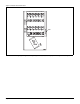
RETURN
FAN
“X” "Y" "XX" "YY"
IN.MMIN.MMIN.MMIN.MM
NONE 24.0 610 82.0 2083 6.8 173 1.5 38
(2) 15" FC 24.0 610 82.0 2083 6.8 173 1.5 38
30" AF 30.0 762 76.0 1930 6.8 173 4.5 114
40" AF 36.0 914 78.0 1981 14.8 376 3.5 89