
Installation manual


Page 18 IM-487
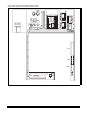
Post and Rail Mounting
When mounting by post and rail, the structural support
should run the full length of the unit. Locate the structural
member at the base of the unit as shown in Figure 17.
If resilient material is placed between the unit and the rail,
insert a heavy steel plate between the unit and the resilient
material to distribute the load. Seal cabinet penetrations
(electrical, piping, etc.) properly to protect against moisture
and weather.
Figure 17. Post and Rail Mounting
Maximum recommended width for structural member is 5" (127 mm) to
allow for adequate space for duct connections and electrical entry.
Rigging and Handling
Lifting brackets with 2" (51 mm) diameter holes are provided
on the sides of the unit.
Use spreader bars, 101" to 105" (2565 to 2667 mm) wide to
prevent damage to the unit cabinet. Avoid twisting or uneven
lifting of the unit. The cable length from the bracket to the
hook should always be longer than the distance between the
outer lifting points.
If the unit must be stored at the construction site for an inter-
mediate period, take these additional precautions:
1. Support the unit well along the length of the base rail.
2. Level the unit (no twists or uneven ground surface).
3. Provide proper drainage around the unit to prevent flood-
ing of the equipment.
4. Provide adequate protection from vandalism, mechanical
contact, etc.
5. Securely close the doors.
6. Cover the supply and return air openings on units without
isolation dampers.
7. Fully close the factory installed isolation dampers to pre-
vent the entry of animals and debris through the supply
and return air openings.
Note: Refer to “Unit Storage” on page 84.
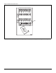
Figure 18 shows an example of the rigging instruction label
shipped with each unit.
Figure 18. Rigging and Handling Instruction Label
CAUTION
The unit must be level side to side and over the
entire length.
Equipment damage can result if the unit is not level.
5" *
(127mm)
99" RAH
(2515 mm)
94" RDS
(2388 mm)
WARNING
Use all lifting points.
Severe personal injury and property damage can result
from improper lifting adjustment.
A
Spreader Bars
Required
Caution:
Lifting points may not
be symmetrical to center of
gravity of unit. Balast or unequal
cable lengths may be required
Unit has either four or six lifting points (four-point shown below).
Caution: All lifting points must be used.
Note:
Rigging cables must be at least as long as distance "A".
Rigging and Handling Instructions
Lift Only As Indicated