
Installation manual


Page 60 IM-487
Unit Options
Enthalpy Control
Outside Air Enthalpy Control (OAE)
Units with MicroTech II control and an economizer come
standard with an electromechanical enthalpy control device
(OAE) which senses both the humidity and temperature of
the outside air entering the unit. This device has an enthalpy
scale marked A through D. Table 12 shows the control points
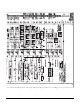
at 50% RH for settings A through D. Figure 55 shows this
scale on a psychrometric chart. When the outside air condi-
tions exceed the setting of the device, the outside air dampers
are positioned to the minimum outside air intake position by
the MicroTech II controller.
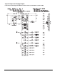
Table 12: Enthalpy control settings
Differential Enthalpy Control (OAE/RAE)
An optional electric differential enthalpy control arrangement
(OAE/RAE) is available on units with MicroTech II control.
In this configuration a solid-state humidity and temperature
sensing device is located in both the return (RAE) and out-
side intake (OAE) airstreams. This OAE device has the same
A through D scale as the device described above. However,
with the OAE/RAE arrangement the switch on OAE must be
set all the way past the "D" setting. With this done, the
MicroTech II controller will adjust the return and outside air
dampers to use the airstream with the lowest enthalpy.
Figure 55. Enthalpy control settings
Ground Fault Protection
The ground fault protection is designed to protect motors
from destructive arcing ground faults. The system consists of
a ground fault relay and a ground fault current sensor. The
ground fault relay employs solid state circuits that will
instantaneously trip and open a set of relay contacts in the
115 volt control circuit to shut the unit down whenever a
ground fault condition exists. The ground fault relay is self
powered. The ground fault sensor is a current transformer
type of device located on the load side of the power block
through which the power wires of all phases are run.
Phase Voltage Monitor
The phase voltage monitor protects against phase loss (single
phasing) when any one of three line voltages drops to 74% or
less of setting. This device also protects against phase rever-
sal when improper phase sequence is applied to equipment,
and low voltage (brownout) when all three line voltages drop
to 90% or less of setting. An indicator run light is "on" when
all phase voltages are within specified limits. The phase volt-
age monitor is located on the load side of the power block
with a set of contacts wired to the 115 volt control circuit to
shut the unit down whenever the phase voltages are outside
the specified limits.
External Time Clock
An external time clock can be used as an alternative (or in
addition) to the MicroTech II controller's internal scheduling
function. The external timing mechanism is set up to open
and close the circuit between field terminals 101 and 102.
When the circuit is open, power is not supplied to digital
input DI (terminal DH1-1)on the ADI board. This is the nor-
mal condition in which the programmable internal schedule
is followed. When the circuit is closed, power is fed to DH1-
1. The MicroTech II controller responds by placing the unit
in the occupied mode, overriding any set internal schedule.
For more information, please see the "Digital Inputs" sec-
tion of Bulletin No. IM 696, "MicroTech II Applied Roof-
top Unit Controller."
Smoke Detectors
Optional smoke detectors can be located at the supply and
return openings. The wiring for these smoke detectors is
shown on any of the "Typical Main Control Circuit" wiring
schematics within the section “Wiring Diagrams” on page 48.
The sequence of operation for these detectors is as follows:
When the smoke is detected by either sensor, the normally
closed sensor contacts open. This removes power from digi-
tal input MCB BI 18 on the Main Control Board.
The MicroTech II controller responds by shutting the unit
down. The controller is placed in the Alarm Off state, and
cannot be restarted until the alarm is manually cleared. Refer
to the operation manual supplied with the unit for informa-
tion on clearing alarms (OM138 or Om137).
The smoke detectors themselves must be manually reset once
they have tripped. Power must be cycled to the smoke detec-
tor to reset.
CONTROL CURVE
CONTROL POINT
TEMP. AT 50% RH
A 73°F (23°C)
B 70°F (21°C)
C 67°F (19*C)
D 63°F (17°C)
3 5
( 1 . 5 )
4 0
( 4 . 5 )
4 5
( 7 )
5 0
( 1 0 )
6 0
( 1 5 . 5 )
6 5
( 1 8 . 5 )
7 0
( 2 1 )
7 5
( 2 4 )
8 0
( 2 6 . 5 )
8 5
( 2 9 . 5 )
9 0
( 3 2 )
9 5
( 3 5 )
1 0 0
( 3 8 )
1 0 5
( 4 0 . 5 )
5 5
( 1 3 )
1 2
1 4
1 6
1 8
2 0
2 2
2 4
2 6
3 0
3 2
3 4
3 6
3 8
4 0
4 2
4 4
4 6
2 8
E N T H A L P Y B T U P E R P O U N D D R Y A I R
C
B
A
D
D
C
B
A
0 . 5 0
0 . 4 0
0 . 3 0
0 . 2 0
0 . 1 0
0 . 6 0
0 . 7 0
0 . 8 0
0 . 9 0
R E L A T I V E
H U M I D I T Y
3 5
( 1 . 5 )
4 0
( 4 . 5 )
4 5
( 7 )
5 0
( 1 0 )
5 5
( 1 3 )
6 0
( 1 5 . 5 )
6 5
( 1 8 . 5 )
7 0
( 2 1 )
7 5
( 2 4 )
8 0
( 2 6 . 5 )
8 5
( 2 9 . 5 )
9 0
( 3 2 )
9 5
( 3 5 )
1 0 0
( 3 8 )
1 0 5
( 4 0 . 5 )