
Installation manual


IM-487 Page 77
Mounting and Adjusting Motor Sheaves
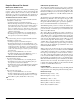
Figure 75. VM and VP variable pitch sheaves
VM and VP Variable Pitch Sheaves
Mounting:
1. Mount all sheaves on the motor shaft with setscrew "A"
toward the motor (see Figure 75).
2. Both the driving and driven sheaves must be in alignment
and the shafts must be parallel.
3. Fit internal key "D" between sheave and shaft, and lock
setscrew "A" securely in place.
Adjusting:
1. Slack off all belt tension by moving the motor toward the
driven shaft until the belts are free from the grooves. For
easiest adjustment, remove the belts.
2. Loosen setscrews "B" and "C" in the moving parts of the
sheave and pull out external key "E" (see Figure 75). This
key projects a small amount to provide a grip for removing.
3. Adjust the sheave pitch diameter for the desired fan speed
by opening the moving parts by half or full turns from
closed position. Do not open more than five full turns
for "A" belts or six full turns for "B" belts.
Adjust both halves of two-groove sheaves by the same
number of turns from closed to verify that both grooves
have the same pitch diameter.
4. Replace external key "E" and securely tighten setscrews
"B" over the key. Tighten setscrews "C" into the keyway
in the fixed half of the sheave.
5. Put on belts and adjust the belt tension. Do not force belts
over grooves. Loosen the belts by adjusting the motor
base closer to the fan shaft.
6. All keys must be in place and all setscrews must be tight
before starting the drive. Check the setscrews and belt ten-
sion after 24 hours of service.
LVP Variable Pitch Sheaves
Mounting:
1. For single-groove sheaves, slide the sheave onto the
motor shaft so that the side of the sheave with setscrew
"A" is next to the motor (see Figure 76 on page 78).
For two-groove sheaves, slide the sheave onto the motor
shaft so that the side of the sheave with setscrew "A" is
away from the motor (see Figure 76 on page 78).
2. To remove the flange and locking rings:
a. Loosen setscrews "D".
b. Loosen but do not remove capscrews "E".
c. Remove key "F". This key projects a small amount to
provide a grip for removing.
d. Rotate the flange counterclockwise until it disengages
the threads on the shaft barrel.
3. Be sure that the driving and driven sheaves are in align-
ment and the shafts are parallel. When aligning two-
groove sheaves, allow room between the sheave and
motor to get to capscrews "E".
4. Insert key "C" between the sheave and the shaft and
tighten setscrew "A" securely.
T w o G r o o v e
C
A
B
B
D
E
C
A
D
E
D
C
S i n g l e G r o o v e
K e y " E " p r o j e c t s
t o p r o v i d e a g r i p
f o r r e m o v a l .
D o n o t o p e r a t e
s h e e v e s w i t h f l a n g e
p r o j e c t i n g b e y o n d
t h e h u b e n d .