
Installation manual


Page 78 IM-487
Adjusting:
1. Slack off all belt tension by moving the motor toward the
driven shaft until the belts are free from the grooves. For
easiest adjustment, remove the belts.
2. Loosen setscrews "D".
3. Loosen but do not remove capscrews "E".
4. Remove key "F". This key projects a small amount to pro-
vide a grip for removing.
5. Adjust the pitch diameter by opening or closing the mov-
able flange by half or full turns. Note that two-groove
sheaves are supplied with both grooves set at the same
pitch diameter. Both movable flanges must be moved
the same number of turns to verify the same pitch
diameter for satisfactory operation. Do not open
sheaves more than five turns for "A" belts or six turns
for "B" belts.
6. Replace key "F".
7. Tighten setscrews "D" and capscrews "E".
8. Put on the belts and adjust the belt tension. Do not force
belts over grooves. Loosen the belts by adjusting the
motor base closer to the fan shaft.
9. Be sure that all keys are in place and that all setscrews and
all capscrews are tight before starting the drive. Check
and retighten all screws and retension the belts after
approximately 24 hours of operation.
MVP Variable Pitch Sheaves
Adjusting:
1. Slack off belt tension by moving the motor toward the
driven shaft until the belts are free from the grooves. For
easiest adjustment, remove the belts.
2. Loosen both locking screws "A" in outer locking ring, but
do not remove them from the sheave. There is a gap of
approximately .2" (1 mm) between the inner and outer
locking rings. This gap must be maintained for satisfac-
tory locking of the sheave.
If locking screws "A" are removed by accident and the
gap is lost, screw the outer locking ring down until it
touches the inner locking ring. Then back off the outer
ring 1/2 to 3/4 turn until the inner and outer ring screw
holes are lined up. Reinsert locking screws "A", but do not
tighten them until after adjustment is made.
3. Adjust the sheave to the desired pitch diameter by turning
the outer locking ring with a spanner wrench. Any pitch
diameter can be obtained within the sheave range. One
complete turn of the outer locking ring will result in a
0.233" (6 mm) change in pitch diameter.] Do not open
"A-B" sheaves more than 43/4 turns for "A" belts or 6
turns for "B" belts. Do not open "C" sheaves more
than 9-1/2 turns.
4. Tighten both locking screws "A" in the outer locking ring.
5. Put on the belts and adjust the belt tension. Do not force
belts over grooves. Loosen the belts by adjusting the
motor base closer to the fan shaft.
Caution:Do not loosen any screws other than the two locking
screws "A" in the outer locking ring. These screws must be
tightened securely before the drive is operated.
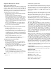
Figure 76. LVP variable pitch sleeves
S e c t i o n A - A S e c t i o n A - A
A
B
C
D
E
F
D
E
A
E
C
F
D
A
A