
Instruction manual
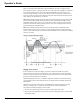
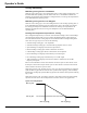
Table Of Contents
- Introduction
- Using the Keypad/Display
- Keypad/Display Menu Structure
- System Summary Menu
- Standard Menus
- System Menu
- Occupancy Menu
- Temperature Menu
- Flow Summary Menu
- Supply Fan Speed Menu
- Return/Exhaust Fan Speed Menu
- Cooling Menu
- Head Pressure Menu
- Evap Condensing Menu
- Economizer Menu
- Min OA Damper Menu
- Heating Menu
- Energy Recovery
- Dehumidification Menu
- Daily Schedule Menu
- One Event Schedule Menu
- Holiday Schedule Menu
- Optimal Start Menu
- Operating Hours Menu
- Extended Menus
- Unit Setup Menu
- Timer Settings Menu
- Time/Date Menu
- Supply Fan Setup Menu
- Return/Exhaust Fan Setup Menu
- Zone Temperature Setup Menu
- Compressor Setup Menu
- Head Pressure Setup Menu
- Chilled Water Setup Menu
- Economizer Setup Menu
- Design Flow Setup Menu
- Heating Setup Menu
- Dehumidification Setup Menu
- Alarm Out Configuration Setup Menu
- Alarm Limits Setup Menu
- Manual Control Menu
- LON/BACnetIP/BACnetMSTP Setup Menu
- Active Alarm Menu
- Alarm Log Menu
- Advanced Menus
- Unit Configuration Setup Menu
- Save/Restore Menu
- Alarm Delays Setup Menu
- Analog Input Status Menu
- Universal I/O Status Menu
- Digital Input Status Menu
- Digital Output Status Menu
- Adv Setup Settings Menu
- Adv Status Parameters Menu
- Alarms
- Operator’s Guide
- Determining Unit State
- Off Operating State
- Start Up Operating State
- Recirculating Operating State
- Heating
- Economizer
- Mechanical Cooling
- Determining Unit Status
- Determining Control Mode
- Determining Cooling Status
- Determining Heat Status
- Determining Economizer Status
- Determining Cooling Capacity
- Determining Heating Capacity
- Determining Supply Air Fan Capacity
- Determining RF/EF Capacity
- Determining Outside Air Damper Position
- Determining Emergency Mode
- Determining Application Mode
- Determining Occupancy Status
- Determining Occupancy Mode
- Determining Occupancy Source
- Unoccupied Operation
- Scheduling
- Temperature Control Configurations
- Heat/Cool Changeover
- Dehumidification
- Energy Recovery
- Outside Air Damper Control
- Outside Air Damper Control, Two Position
- Special Procedures for Units with WRV and More Than Two Circuits.
- Water Pump Control
- Cooling: Multistage
- Cooling: Modulating
- Heating Control
- Modulating
- Min DAT
- Indoor Air Fan - On/Off Control

McQuay OM 920 109
Operator’s Guide
• DAT is greater than the effective DAT setpoint (DAT staging) or the MIN DAT limit
(MinDAT staging) by ½ the deadband
OR
• The current heating stage is more than the number of available heating stages
The unit enters the Min DAT operating state during occupied operation when neither cooling
nor heating is required based on the unit heat/cool changeover function but the discharge air
temperature falls below a minimum discharge temperature limit by more than ½ the deadband.
The Min DAT operating state prevents cold discharge air temperatures during what would
normally be the Fan Only operating state.
Modulating
Entering Heating Operating State
The unit enters the Heating operating state from the Fan Only operating state when the control
temperature falls below the Zone Heating Set Point by more than half the Zone Heating Dead
Band. The unit transitions from heating to Fan only when the control temperature rises above
the Zone Heating Set Point by more than half the Zone Heating Dead Band. The unit will also
transition from the Heating to Fan only operating state if heating operation is disabled due to
OA ambient lockout. When the unit is in the Heating operating state, heating capacity is
modulated to maintain the discharge air temperature at the Discharge Heating Set Point.
There are several different modulating heating types available with this equipment. There are
some differences in the control sequence depending on the heat type installed. The different
types are described in the following sections.
Steam or Hot Water Heat: Face and Bypass Damper Control
When a unit is equipped with steam or hot water with face and bypass damper heating there
are two different methods used for controlling the heating arrangement. These are the “Open
Valve” and “Modulating Valve” methods and are described in the following sections. The
parameter is adjustable via the following path: Extended Menus/Heating Setup/F&BP
Method.
Open Valve
When the unit enters the Heating operating state, the steam or hot water valve is driven fully
open. The face and bypass dampers are then modulated to maintain the discharge air
temperature at the discharge heating set point.
Modulating Valve
When the Outdoor Air Temperature is below the F&BP changeover temperature by the
amount of the differential, the Heating valve is driven to 100% open to protect the coil. The
face and bypass dampers are then modulated to satisfy the heating load. At warmer
temperatures, the Face and Bypass Dampers are set at 100% open to the face of the coil and
the Heating valve is modulated to satisfy the heating load. Operation changes from “warm” to
“cool” when the outdoor air temperature drops below the changeover temperature. It changes
from “cool” to “warm” when the outdoor air temperature rises above the F&B Changeover
temperature by a differential of 2.0ºF. The default value for the changeover temperature is
37°F.