
Instruction manual
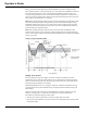
Table Of Contents
- Introduction
- Using the Keypad/Display
- Keypad/Display Menu Structure
- System Summary Menu
- Standard Menus
- System Menu
- Occupancy Menu
- Temperature Menu
- Flow Summary Menu
- Supply Fan Speed Menu
- Return/Exhaust Fan Speed Menu
- Cooling Menu
- Head Pressure Menu
- Evap Condensing Menu
- Economizer Menu
- Min OA Damper Menu
- Heating Menu
- Energy Recovery
- Dehumidification Menu
- Daily Schedule Menu
- One Event Schedule Menu
- Holiday Schedule Menu
- Optimal Start Menu
- Operating Hours Menu
- Extended Menus
- Unit Setup Menu
- Timer Settings Menu
- Time/Date Menu
- Supply Fan Setup Menu
- Return/Exhaust Fan Setup Menu
- Zone Temperature Setup Menu
- Compressor Setup Menu
- Head Pressure Setup Menu
- Chilled Water Setup Menu
- Economizer Setup Menu
- Design Flow Setup Menu
- Heating Setup Menu
- Dehumidification Setup Menu
- Alarm Out Configuration Setup Menu
- Alarm Limits Setup Menu
- Manual Control Menu
- LON/BACnetIP/BACnetMSTP Setup Menu
- Active Alarm Menu
- Alarm Log Menu
- Advanced Menus
- Unit Configuration Setup Menu
- Save/Restore Menu
- Alarm Delays Setup Menu
- Analog Input Status Menu
- Universal I/O Status Menu
- Digital Input Status Menu
- Digital Output Status Menu
- Adv Setup Settings Menu
- Adv Status Parameters Menu
- Alarms
- Operator’s Guide
- Determining Unit State
- Off Operating State
- Start Up Operating State
- Recirculating Operating State
- Heating
- Economizer
- Mechanical Cooling
- Determining Unit Status
- Determining Control Mode
- Determining Cooling Status
- Determining Heat Status
- Determining Economizer Status
- Determining Cooling Capacity
- Determining Heating Capacity
- Determining Supply Air Fan Capacity
- Determining RF/EF Capacity
- Determining Outside Air Damper Position
- Determining Emergency Mode
- Determining Application Mode
- Determining Occupancy Status
- Determining Occupancy Mode
- Determining Occupancy Source
- Unoccupied Operation
- Scheduling
- Temperature Control Configurations
- Heat/Cool Changeover
- Dehumidification
- Energy Recovery
- Outside Air Damper Control
- Outside Air Damper Control, Two Position
- Special Procedures for Units with WRV and More Than Two Circuits.
- Water Pump Control
- Cooling: Multistage
- Cooling: Modulating
- Heating Control
- Modulating
- Min DAT
- Indoor Air Fan - On/Off Control

110 McQuay OM 920
Operator’s Guide
Gas Heat
When a unit is equipped with modulating gas heating and is in the Heating operating state, the
gas valve is modulated to maintain the discharge air temperature at the Discharge Heating Set
Point. Differences in the control of modulating gas heat are described in the following
sections. On units equipped with modulating gas heat, the Discharge Heating Set Point is
limited according to a maximum heat exchanger temperature rise limit. This factory set limit
varies depending on the unit burner model and can be found on the gas heat data plate attached
to the unit. The controller does not allow the Discharge Heating Setpoint to be set above the
current temperature entering the discharge fan by more than this maximum heat exchanger
temperature rise limit.
Min DAT
If heating is enabled and there is no heating load (normally Fan Only operating state), the
controller activates the units heating equipment as required to prevent the discharge air
temperature from becoming too cool if the Min DAT Control Flag is set to yes via the Heating
menu. The unit enters the Min DAT operating state during occupied operation when neither
cooling nor heating is required based on the heat/cool changeover function but the discharge
temperature falls below a minimum discharge temperature limit. If the discharge air
temperature falls below the this minimum discharge temperature limit by more than half the
discharge heating deadband, the unit operating state changes from Fan Only to Min DAT.
Note: On VAV or CAV discharge control units, the DAT cooling setpoint parameter in the
Cooling menu acts as the minimum discharge temperature limit. On CAV zone control units
the Min DAT Limit parameter in the Heating menu acts as the minimum discharge
temperature limit.
Typical Sequence of Operation (20-1 gas burner)
When 120V power is furnished through the system on/off switch (S1), through the burner
on/off switch (S3), and through the high limit control (FLC), terminal #6 on the flame
safeguard (FSG) is powered on a call for heat. Whenever power is restored to the flame
safeguard, the flame safeguard will go through a 10 second initiation period before the
prepurge period will begin. The burner air control valve will be at minimum position during
off cycles. Upon a call for heat or any other time that a prepurge cycle occurs, the air control
valve will be repositioned to the maximum position for prepurge and then returned to the
minimum position for low fire start.
Upon a call for heat, the controller will close digital output (EXPB-DO1) and energize the
R20A relay. Once the normally open contacts of the R20A relay close 120V power is supplied
to terminal # 6 on the FSG. The FSG then energizes its terminal #4, which powers the burner
combustion air blower motor (BM) and starts the 90 second prepurge cycle. The controller
will reposition the burner air valve to its maximum open position via analog output EXPB-
AO_X7 for prepurge. When the burner air valve reaches the full open position switch (LS2)
will 'make' and provide a digital input to the controller (EXPB-DI_X3). This digital input will
initiate a 20 second (adjustable) timing period in the controller. At the completion of the
timing period, the controller will begin to drive the burner air valve to its minimum (low fire)
position. When the valve reaches the minimum position switch LS1 will 'make' and provide a
digital input to the controller (EXPB-DI_X2) indicating the controller's prepurge sequence is
complete. As soon as the FSG prepurge time expires FSG terminal #8 will energize relay R22
which will turn on a digital input to the controller (EXPB-DI-X1). As soon as this digital input
is 'made' the controller will close digital output (EXPB-DO2) allowing the combination gas
valve(s) (GV1) to be energized.