
Instruction manual
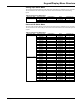
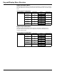
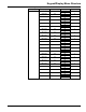
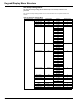


Table Of Contents
- Introduction
- Using the Keypad/Display
- Keypad/Display Menu Structure
- System Summary Menu
- Standard Menus
- System Menu
- Occupancy Menu
- Temperature Menu
- Flow Summary Menu
- Supply Fan Speed Menu
- Return/Exhaust Fan Speed Menu
- Cooling Menu
- Head Pressure Menu
- Evap Condensing Menu
- Economizer Menu
- Min OA Damper Menu
- Heating Menu
- Energy Recovery
- Dehumidification Menu
- Daily Schedule Menu
- One Event Schedule Menu
- Holiday Schedule Menu
- Optimal Start Menu
- Operating Hours Menu
- Extended Menus
- Unit Setup Menu
- Timer Settings Menu
- Time/Date Menu
- Supply Fan Setup Menu
- Return/Exhaust Fan Setup Menu
- Zone Temperature Setup Menu
- Compressor Setup Menu
- Head Pressure Setup Menu
- Chilled Water Setup Menu
- Economizer Setup Menu
- Design Flow Setup Menu
- Heating Setup Menu
- Dehumidification Setup Menu
- Alarm Out Configuration Setup Menu
- Alarm Limits Setup Menu
- Manual Control Menu
- LON/BACnetIP/BACnetMSTP Setup Menu
- Active Alarm Menu
- Alarm Log Menu
- Advanced Menus
- Unit Configuration Setup Menu
- Save/Restore Menu
- Alarm Delays Setup Menu
- Analog Input Status Menu
- Universal I/O Status Menu
- Digital Input Status Menu
- Digital Output Status Menu
- Adv Setup Settings Menu
- Adv Status Parameters Menu
- Alarms
- Operator’s Guide
- Determining Unit State
- Off Operating State
- Start Up Operating State
- Recirculating Operating State
- Heating
- Economizer
- Mechanical Cooling
- Determining Unit Status
- Determining Control Mode
- Determining Cooling Status
- Determining Heat Status
- Determining Economizer Status
- Determining Cooling Capacity
- Determining Heating Capacity
- Determining Supply Air Fan Capacity
- Determining RF/EF Capacity
- Determining Outside Air Damper Position
- Determining Emergency Mode
- Determining Application Mode
- Determining Occupancy Status
- Determining Occupancy Mode
- Determining Occupancy Source
- Unoccupied Operation
- Scheduling
- Temperature Control Configurations
- Heat/Cool Changeover
- Dehumidification
- Energy Recovery
- Outside Air Damper Control
- Outside Air Damper Control, Two Position
- Special Procedures for Units with WRV and More Than Two Circuits.
- Water Pump Control
- Cooling: Multistage
- Cooling: Modulating
- Heating Control
- Modulating
- Min DAT
- Indoor Air Fan - On/Off Control

McQuay OM 920 59
Alarms
Entering Water Temperature Sensor Problem
If the entering water temperature sensor (EWT) is present and either shorted or open circuited
for longer than the Sensor Alarm Delay (default is 30 seconds), the EWT Sensor problem
occurs. When the EWT Sensor problem occurs, waterside economizer cooling is disabled.
Mechanical cooling is not locked out based on EWT. When the alarm condition is no longer
present, the EWT Sensor problem automatically clears.
Mixed Air Temperature Sensor Problem
If the Mixed Air Temperature Sensor (MAT) is present and either shorted or open circuited for
longer than the Sensor Alarm Delay (default is 30 seconds), the MAT Sensor problem occurs.
When the MAT Sensor problem occurs, waterside economizer cooling is disabled. When the
alarm condition is no longer present, the MAT Sensor problem automatically clears.
Freeze Problem
When a unit is equipped with a waterside economizer, chilled water, hot water, or steam coil,
the Freeze problem occurs when the optional freezestat contacts open as a result of detecting
an abnormally low water or steam coil temperature while the fans are off.
When the Freeze problem occurs, the controller opens the waterside economizer valve, chilled
water and heating valves and set a 10-minute timer. If the unit is equipped with a waterside
economizer, the pump output is also turned on. When the 10-minute timer expires, the
controller checks the freezestat input again. If the freezestat contacts are closed the pump
output is de-energized and the valves close. If the freezestat contacts are still open the pump
output remains energized, the valves remain open, and the 10-minute timer resets. This
continues while the unit remains off. Whenever the freezestat closes the Freeze problem
automatically clears. This feature protects the coil(s) and allows the system to start normally
when an occupied command is received.
Fan Retry Problem
On units equipped with a discharge fan VFD, the Fan Fail fault only occurs if the Fan Retry
problem described below has first occurred twice within the previous twenty-four hour period.
The conditions that cause the Fan Retry problem and the action taken are the same as for the
Fan Fail fault with the difference being that the Fan Retry alarm is an automatically clearing
alarm once the unit is shut off. This allows the unit to attempt to restart up to three times
within a twenty-four hour period.
The Fan Retry conditions are:
• The Supply Fan is controlled by a VFD
• No Faults that would shut down the unit are active
• Airflow Switch is Open AND the duct static pressure is less than half of the Duct Static
Pressure Setpoint
• The Supply Fan has been on for longer than the Airflow Timer (Default =120 seconds)
• The unit is not in Post Heat Operation and has not been in Post Heat Operation for longer
than 120 seconds. This means that this alarm is disabled during and after post heat operation
The Fan Fail alarm is initiated if these conditions are encountered three times between 2:00
am of one day and 2:00 am the following day. If the Fan Fail alarm is then cleared, the process
may be repeated so that the unit may be shut down up to three more times.