Installation and Maintenance Manual Skyline Air Handler IM 777-5 Group: Applied Air Systems Part Number: IM 777 Date: May 2010 Models OAC/OAH 003G – 090G ® © 2010 McQuay International
Contents Introduction . . . . . . . . . . . . . . . . . . . . . . . . . . . . . . . 3 General Information . . . . . . . . . . . . . . . . . . . . . . . 3 Receiving and Handling . . . . . . . . . . . . . . . . . . . . 3 Unit Storage . . . . . . . . . . . . . . . . . . . . . . . . . . . . . 3 Nomenclature . . . . . . . . . . . . . . . . . . . . . . . . . . . . 3 Mechanical Installation . . . . . . . . . . . . . . . . . . . . . . 4 Service Clearances . . . . . . . . . . . . . . . . . . . . . . . 4 Rigging . .
Introduction Introduction General Information inspect all units for shipping damage. Report damage immediately to the carrier and file a claim. The system design and installation must follow accepted industry practice as described in the ASHRAE Handbook, the National Electric Code, and other applicable standards. Install this equipment in accordance with regulations of authorities having jurisdiction and all applicable codes.
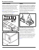
Mechanical Installation Mechanical Installation Service Clearances Rigging In addition to providing adequate space around the unit for piping coils and drains, access to at least one side of the unit is always required to allow for regular service and routine maintenance, which includes filter replacement, drain pan inspection and cleaning, fan bearing lubrication, and belt adjustment. Provide sufficient space—at least equal to the length of the coil—on the side of the unit for coil removal.
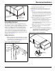
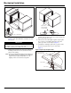
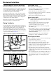
Mechanical Installation Figure 4: Leveling the Unit 2 Pull sections together to fasten. Use straps and a ratchet to help pull the sections together securely. Apply sealant to any gaps that may admit moisture. 3 Fasten base rails together first using the 3/8"-16 × 5" bolts located in the splice kit provided with the unit (Figure 7). a To fasten two shipping sections together, four bolts are needed (two on each side of the unit). The bolts are run from one base rail into the other and fastened with a nut.
Mechanical Installation Figure 7: Fasten Bottom of Section Figure 8: Internal Fastening “D” Gasket A S p lic e C o lla r m u s t b e a lig n e d to s e a l to g a s k e t. 3/8" x 1" Bolt and Nut 1 Check that the sealant is compressed between the mating d A length of “D” gasket is attached to each section (Figure 7). This gasket MUST be installed to the unit base section.
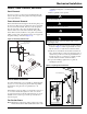
Mechanical Installation Panels, Frame Channels, and Doors Panel Removal that require the “use of tools” to access compartments containing moving parts or electrical wiring. See Figure 11. 1 Remove padlock if one is present. To remove a side or top panel, remove the flat head Torx 30 fasteners along the sides of the panel. Lift off the panel after removing all fasteners. CAUTION Sharp edges and coil surfaces are a potential injury hazard. Avoid contact with them.
Mechanical Installation Injected-Foam Insulated Panels Skyline air handlers now are furnished with double-wall, injected-foam insulated panels. Foam panels are stronger, more rigid, and lighter than panels with fiberglass insulation. The insulation R-value is improved to 13. However, foam insulation can burn when exposed to flame or other ignition sources and release toxic fumes. Take care in cutting and sealing all field-cut openings in these panels.
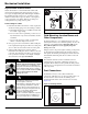
Mechanical Installation If the unit has a top mixing box or economizer damper or a top duct connection, field fabricate and install flashing to divert moisture from the connection. The flashing must lap over the standing seams of the top panels. The flashing also must lap over the side edges of the unit (Figure 14).
Mechanical Installation Face and Bypass Section Mounting Piping and Coils Internal and external face and bypass sections are mounted together using the instructions for horizontal components and do not require additional instruction. Skyline air handlers are provided with a bypass duct that is integral to the unit construction and requires no field assembly. When designing and installing piping: Face and bypass dampers may or may not be linked together.
Mechanical Installation Steam Coils • Multiple coil installation—individually trap each coil or group of coils. Piping (see Figure 19) • Steam supply and steam return connections typically are male NPT iron pipe and are labeled on the end panel of coil section. Connections extend through the coil section end panel. • Coils in series—use separate traps for each coil, or a bank of coils. • When installing couplings, do not apply undue stress to the connection extending through unit panel.
Mechanical Installation Figure 19: Piping Arrangements Float and thermostatic trap Check Valve Strainer Control valve modulating two position Gate Valve High Pressure (over 25 psi) Vacuum breaker 1/2" check valve Steam main Vacuum breaker 1/2" check valve 1/4" petcock for continuous air venting Steam main Return main 1" min. 12" min. 1/4" petcock for continuous air venting High pressure float or bucket trap 1" min. 12" min. High pressure bucket trap Full size of return conn.
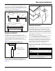
Mechanical Installation Water Heating Coils Figure 20: Allow Adequate Distance Between Trap Outlet and Drain Pan Outlet CAUTION Improper installation, use, or maintenance of water heating coils can cause equipment damage. Read and follow instructions carefully. Pressure (P) at the drain pan 2P ATTENTION Si l’installation, l’utilisation ou l’entretien des serpentins de chauffage à eau sont inadéquats, ceci endommagera l’équipement. Lire et suivre attentivement les instructions.
Mechanical Installation Internal Isolation Assembly Adjustment Table 2: Motor Behind Fan Spring Mount Adjustments On units with internally isolated fan and motor assemblies, the assemblies are secured for shipment. with a tie-down at each point of isolation. Before Operating the Unit: Remove the shipping brackets and tie-down bolts (see Figure 23 and Figure 24) and discard. The shipping brackets located on the opposite drive side of the unit are difficult to access from the drive side of the unit.
Mechanical Installation Figure 23: Removing “Motor Behind” Shipping Brackets Unit sizes 006 - 090 Figure 24: Removing “Motor Beside” Shipping Brackets Unit sizes 006 - 090 S h ip p in g h o ld d o w n r e m o v e a n d d is c a r d ( T y p ic a l 4 p la c e s ) S h ip p in g b r a c k e t r e m o v e a n d d is c a r d ( T y p ic a l 4 p la c e s ) S e e d e ta il " A " S p r in g h e ig h t a d ju s tm e n t s c r e w D im "H " P O S 2 P O S 3 M o to r A ir flo w F a n P O S 1 P O S 4 F a n is o
Electrical Installation Electrical Installation Wiring Figure 25: Electrical Conduit Location DANGER Capacitor hazardous voltage! Failure to disconnect power and discharge capacitors before servicing will result in serious injury or death. Disconnect all electric power (including remote disconnects) before servicing. Perform lockout/tagout procedures to ensure that power can not be energized.
Operation Guidelines Operation Guidelines Startup Checks ATTENTION When performing startup and service, always take thorough safety precautions. Only trained, experienced personnel should perform these functions. WARNING Rotating fan. Can cause severe injury or death. Before servicing fans, lockout and tag out power. AVERTISSEMENT Ventilateur en rotation. Peut causer des blessures sévères ou même la mort. Avant d’effectuer l’entretien des ventilateurs, bloquer et couper la tension.
Operation Guidelines Note: Variable pitch fan drives usually are provided for operation in the mid-speed adjustment range. However, the drives usually ship with the adjustment opened up for minimum fan speed. Adjust the drives for the proper airflow. See Fan Drive‚ page 23.
Operation Guidelines Figure 29: Wheel-to-Inlet Funnel Relationship—40 to 60 Plenum Fans Cross Section Reference A FUNNEL END TO FAN WHEEL OPENING EQUALLY SPACED AROUND DIAMETER B 27 3/8 19.2 22 30 1/2 41.7 55 33 1/2 41.7 55 36 1/2 41.7 55 40 1/2 41.7 55 44 1/2 41.7 55 49 1/2 41.7 55 54 1/2 41.
Operation Guidelines Operating Limits Do not exceed the operating limits in Table 10. A fan wheel operated beyond the rpm and temperature limits shown can suffer permanent distortion or fracture. The resulting unbalance can cause severe unit vibration. Table 10: Unit Sizes 003 to 035 Fan operating limits Forward curved—housed Diameter 9×4 9×7 9×9 10.62 12.62 15 18 20 22.25 Maximum rpm Class I N/A 2189 2223 1934 1614 1328 1155 1050 944 24.
Operation Guidelines Table 12: Operating Limits—Plenum Fans Fan operating limits Plenum fans Diameter Class Maximum rpm 13.5 15 16.5 18.25 20 22.25 24.5 27 30 33 36.5 2 2 2 2 2 2 2 2 2 2 2 40.25 44.50 2 2 49 54.25 60 2 2 2 986 891 75 75 3,909 3,468 2,820 2,930 2,674 2,403 2,183 1,860 1,783 1,620 1,465 1,329 1,202 1,091 Maximum motor HP 7.
Service and Maintenance Service and Maintenance Periodic Maintenance 1 Check all moving parts for wear every six months. 2 Check bearing collar, sheave, and wheel hub setscrews, Compatibility of grease is critical. Relubricatable bearings are supplied with grease fittings or zerks for ease of lubrication with hand or automatic grease guns. Always wipe the fitting and grease nozzle clean. sheave capscrews, and bearing hold-down bolts for tightness every six months.
Service and Maintenance 2 Verify that both driving and driven sheaves are in Table 18: Recommended Fan Relubrication Grease Charge Shaft Size (in) 1/2 to 3/4 7/8 to 1-3/16 1-1/4 to 1-1/2 1-11/16 to 1-15/16 2 to 2-7/16 2-1/2 to 2-15/16 3 to 3-7/16 3-1/2 to 4 OZ. 0.03 0.10 0.15 0.20 0.30 0.50 0.85 1.50 Shaft Size 20 mm 25-30 mm 35-40 mm 45-50 mm 55-60 mm 65-70 mm 75-80 mm 85-105 mm Grams 0.85 2.84 4.25 5.67 8.51 15.59 24.10 42.53 alignment and that shafts are parallel.
Service and Maintenance LVP Variable Speed Sheaves 9 Put on belts and adjust belt tension. Do not force belts over grooves. See Fan Drive Belt Adjustment‚ page 27. Mounting 1 Slide sheave on motor shaft so that the side of the sheave with setscrew A is next to the motor when setscrew A is in the hub or barrel of the sheave. 2 When setscrew A is at an angle in the center flange B, 10 Before starting the drive, ensure that all keys are in place and all setscrews and all capscrews are tight.
Service and Maintenance MVP Variable Speed Sheaves into the three holes that are located 120° apart on the ring. Mounting 1 Verify both driving and driven sheaves are in alignment and the shafts are parallel. The centerline of the driving sheave must be in line with the centerline of the driven sheave. See Figure 38, page 26. 2 Verify that all setscrews are torqued to the values shown in Figure 19, page 25 before starting drive. Check setscrew torque and belt tension after 24 hours of service.
Service and Maintenance Figure 38: Sheave Adjustment Must be parallel Bearing Center lines must coincide Motor Adjustable Sheave Must be parallel Figure 39: Sheave Adjustment A d ju s ta b le C e n te r - F la n g e F ix e d C e n te r - F la n g e ( 2 ) L o c k in g S e ts c re w s "A " F la th e a d S o c k e t S c r e w s (D o N o t R e m o v e ) S p lit T a p e r B u s h in g C a p s c re w s (D o N o t R e m o v e ) 26 S ta tio n a r y E n d - F la n g e O u te r L o c k in g - R in g In n
Service and Maintenance Fan Drive Belt Adjustment WARNING General Rules of Tensioning 1 The ideal tension is the lowest tension at which the belt does not slip under peak load conditions. Moving belt and fan can cause severe personal injury or death. During installation and filter maintenance: • Verify that the belt and fan guards on plenum fan units are 2 Check tension frequently during the first 24 to 48 hours of always in place. operation. • Lock and tag out fans to prevent accidental start up.
Service and Maintenance Front Load Filter Option Table 21: Filter Pressure Drops Front loaded filter options require that the filters be removed and replaced from inside the unit. To remove filters, rotate the wire clips. This releases both the prefilter and the final filter. When installing clean filters, check to verify the filters are fully seated in the frame (Figure 41).
Service and Maintenance Winterizing Water Coils Coils can freeze due to air stratification or failure of outdoor air dampers and/or preheat controls. Do not depend on routine draining of water cooling coils for winter shutdown as insurance against freeze-up. Severe coil damage can result. Drain all coils as thoroughly as possible and then treat in the following manner. • Fill each coil independently with an antifreeze solution using a small circulating pump and again thoroughly drain.
Service and Maintenance Figure 43: Single Coil Top Installation/Removal Opposite connection end Connection end Coil Removing Stacked Coils Note: Top and bottom stacked coils are held together with steel plate and screws on one side and drain trough and screws on the other side. Remove the plate and trough before removing the coils. The coils cannot be removed attached together. 1 Disconnect all piping and remove the brass plugs for the vents and drains located in the connections.
Parts Parts Replacement Parts When writing to McQuay for service or replacement parts, refer to the model number and serial number of the unit stamped on the serial plate attached to the unit. If replacement parts are required, mention the date of installation of the unit and date of failure, along with an explanation of the malfunctions and a description of the replacement parts required.
Service and Warranty Procedure Service and Warranty Procedure Warranty Consult your local McQuay Representative for warranty details. Refer to Form 933-43285Y. To find your local McQuay Representative, go to www.mcquay.com. Warranty Return Material Procedure Defective material may not be returned without permission of authorized factory service personnel of McQuay International in Minneapolis, Minnesota, (763) 553-5330. A “Return Goods” tag must be included with the returned material.
Check, Test, and Start Procedure Form Check, Test, and Start Procedure Form To comply with the terms of McQuay Warranty, complete and return this form within 10 days to McQuay Warranty Department. Check, test, and start procedure for McQuay Air Handling Units with or without heat recovery. Job Name:________________________________________ McQuay S.O. No.: _________________ McQuay G.O. No.
Check, Test, and Start Procedure Form Phase L2: ___________ ___________ ____________ ____________ ___________ ___________ Phase L3 ___________ ___________ ____________ ____________ ___________ ___________ G. FLA: L1 ___________ L2 ___________ L3____________ H. Operate electric heat with fans off. Electric heat must cycle OFF on high limit control. . . . . . . . . . . . . . . . . . . . . . . . . . Yes No N/A A. Pressure test okay? . . . . . . . . . . . . . . . . . . . . . . . . . . . .
Quality Assurance Survey Report Quality Assurance Survey Report Quality Assurance Survey Report To whom it may concern: Please review the items below upon receiving and installing our product. Mark N/A on any item that does not apply to the product. Job Name: _____________________________________________________ McQuay G.O. no.
McQuay Training and Development Now that you have made an investment in modern, efficient McQuay equipment, its care should be a high priority. For training information on all McQuay HVAC products, please visit us at www.mcquay.com and click on training, or call 540-248-9646 and ask for the Training Department. Warranty All McQuay equipment is sold pursuant to its standard terms and conditions of sale, including Limited Product Warranty. Consult your local McQuay Representative for warranty details.