
Unit installation


McQuay IM 777 23
Service and Maintenance
Fan Drive
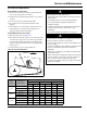
Upon completion of the air balance, replace the variable
pitched motor sheave with a properly sized, fixed sheave. A
matching fixed sheave provides longer belt and bearing life
and minimizes vibration. Initially, it is best to have a variable
pitched motor sheave for the purpose of air balancing. Once
the balance is achieved, fixed sheaves maintain balancing and
alignment more effectively. Replace the adjustable sheaves
with fixed sheaves.
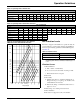
With the electrical power disconnected, locked and tagged out,
measure the diameter of the V-belt outer surface where it
passes around the sheave (pitch diameter). Calculate fan speed
from the motor nameplate rpm.
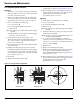
VM and VP Variable Pitch Key Type Sheaves
Mounting
1 Mount all sheaves on the motor or driving shaft with the
setscrews
A toward the motor.
2 Verify that both driving and driven sheaves are in
alignment and that shafts are parallel.
3 Fit internal key D between sheave and shaft and lock
setscrew
A securely in place.
Adjusting
1 Loosen setscrews B and C in moving parts of sheave and
pull out external key
E. (This key projects a small
amount to provide a grip for removing.)
2 To adjust sheave pitch diameter for desired speed, open
moving parts by half or full turns from closed position.
Do not open more than five full turns for
A belts or
six full turns for
B belts.
3 Replace external key E and securely tighten setscrews B
over key and setscrews
C into keyway in fixed half of the
sheave.
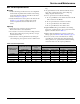
4 Put on belts and adjust belt tension. Do not force belts
over grooves. See Fan Drive Belt Adjustment‚ page 27.
5 Make future adjustments by loosening the belt tension
and increasing or decreasing the pitch diameter of the
sheave by half or full turns as required. Readjust belt
tension before starting drive.
6 To provide the same pitch diameter, adjust both halves of
the two-groove sheaves by the same number of turns
from closed position.
7 Verify that all keys are in place and that all se screws are
tight before starting drive. Check setscrews and belt
tension after 24 hours service.
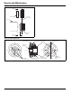
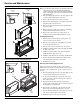
Figure 36: VP Type Sheave Adjustment
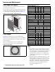
Table 18: Recommended Fan Relubrication Grease Charge
Shaft Size (in) OZ. Shaft Size Grams
1/2 to 3/4 0.03 20 mm 0.85
7/8 to 1-3/16 0.10 25-30 mm 2.84
1-1/4 to 1-1/2 0.15 35-40 mm 4.25
1-11/16 to 1-15/16 0.20 45-50 mm 5.67
2 to 2-7/16 0.30 55-60 mm 8.51
2-1/2 to 2-15/16 0.50 65-70 mm 15.59
3 to 3-7/16 0.85 75-80 mm 24.10
3-1/2 to 4 1.50 85-105 mm 42.53
WARNING
Before servicing fans, lock out and tag out all power to the
unit. Fans or belts can cause severe personal injury or death.
AVERTISSEMENT
Avant de faire le service sur les ventilateurs,couper et
indiquer que le courant est coupé. Les ventilateurs ou les
courroies peuvent causer des blessures personnelles graves
ou entraîner la mort.
WARNING
Do not open the hinged access door and screw-fastened
access panels while the unit is operating. Moving parts and
strong suction forces can cause severe personal injury or
death.
AVERTISSEMENT
Ne pas ouvrir les portes d’accès à charnières et les
panneaux à vis lorsque l’unité fonctionne. Les pièces
mobiles et le niveau de succion peuvent causer des blessures
personnelles graves ou même entraîner la mort.
Fan rpm = motor rpm ×
Measured diameter at motor sheave
Measured diameter at fan sheave
Two Groove
C
A
B
B
D
E
C
A
B
E
D
C
Single Groove
Key E projects
to provide a grip
for removal.
Do not operate
sheeves with flange
projecting beyond
the hub end.