Installation and Maintenance Manual IM-846 Group: Fan Coil Part Number: IM 846 Date: July 2006 T170 Thermostat 24 VAC/120–277 VAC 3-Speed Fan Control (Continuous or Cycling) or Staged Fan Control US © 2006 McQuay International
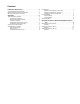
Contents Installation Instructions . . . . . . . . . . . . . . . . . . . . . 3 Thermostat Model and Part Number . . . . . . . . . . . . . . . . . . . . . . . . 3 Optional Occupancy Detection Sensors/Kits . . . . . . . . . . . . . . . . . . 3 Mounting and Wiring the Thermostat . . . . . . . . . . . . . . . . . . . . . . . . 3 Operation . . . . . . . . . . . . . . . . . . . . . . . . . . . . . . . . . 5 Thermostat Button Operation . . . . . . . . . . . . . . . . . . . . . . . . . . . . . .
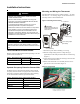
Installation Instructions Installation Instructions Mounting and Wiring the Thermostat WARNING • BEFORE ATTEMPTING TO INSTALL, OPERATE, OR SERVICE THIS THERMOSTAT, CAREFULLY READ THESE INSTRUCTIONS. • Failure to observe safety information and comply with instructions could result in PERSONAL INJURY, DEATH, AND/OR PROPERTY DAMAGE. • To avoid potential fire and/or explosion, do not use in potentially flammable or explosive atmospheres. • Retain these instructions for future reference.
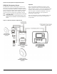
Installation Instructions 5 On the circuit board, set the voltage selection switch Figure 3: Wiring diagram (Figure 2) to the appropriate voltage for the application Setback input/door switch White/Black Note: The circuit board is shipped with the voltage selection switch in the 110-227 V position. For 24 VAC use, the switch must be in the 24 V position. Before applying power, the voltage selection switch must be in the appropriate position.
Operation Operation Thermostat Button Operation UP/Down Arrow Button Operation The thermostat interface (Figure 4) contains buttons for use in navigating to accompanying menus/screens and for performing specific operations. These buttons and operations are described below. Use the Up and Down arrow buttons (Figure 4) to increase or decrease the temperature.
Operation Thermostat Menu Functions The thermostat menu contains nine functions which can be accessed using controls on the thermostat. Accessing the menu functions and details of each function are described below. 5 Range limit high When this function is selected, the current maximum temperature range adjustment, SET POINT icon, and LO icon appear. To increase or decrease the value, press the up or down arrow button.
Operation Fan Operation The thermostat may be factory configured for standard or staged fan operation. Standard Fan Configuration (TA170-001) Units with standard fan operation (Figure 8) have a selectable fan Speed button. Figure 8: Standard fan operation Fan ON: fan is on continuously. Fan AUTO: fan cycles on with demand. S PE ED: Fan s peed is selected by the user .
Operation Fancoil Operation 3 If the water temperature is beyond 15°F of the set point, Fancoil operation is either a 2-pipe or 4-pipe configuration which is determined by jumper selection JP4 (see “Mounting and Wiring the Thermostat” on page 3). 4 If the water temperature is not beyond 15°F of the set point, normal HVAC control occurs. the thermostat checks to see if the water temperature is above 80°F or below 60°F. 2-Pipe Operation If yes, normal HVAC control occurs.
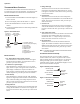
Optional Occupancy Detection Equipment Operation Optional Occupancy Detection Equipment Operation The T170 thermostat can be used with optional S200 series occupancy detection equipment. Purchasing and installing this equipment to compliment the thermostat adds energy savings by setting back HVAC operation during occupied and unoccupied times. Optional detection equipment configurations and operation are described below.
Optional Occupancy Detection Equipment Operation SD200-001 Occupancy Sensor Operation The SD200-001 occupancy sensor (Figure 11) serves as a master sensor for a guest room HVAC management system. The sensor provides HVAC operation according to occupancy status, as well as door/window switch monitoring, selectable high/low temperature setback, form-C output, slave sensor connectivity, and a five minute door open HVAC shut-off.
Optional Occupancy Detection Equipment Operation SD200-002 Occupancy Sensor Operation The SD200-002 occupancy sensor serves as a stand alone master sensor for a guest room HVAC management system. The sensor provides HVAC operation according to occupancy status, as well as selectable high/low temperature setback, form-C output, and a five minute door open HVAC shut-off. This system provides basic room setback and is ideal for control of HVAC in commercial spaces.
McQuay Training and Development Now that you have made an investment in modern, efficient McQuay equipment, its care should be a high priority. For training information on all McQuay HVAC products, please visit us at www.mcquay.com and click on training, or call 540-248-9646 and ask for the Training Department. Warranty All McQuay equipment is sold pursuant to its standard terms and conditions of sale, including Limited Product Warranty. Consult your local McQuay Representative for warranty details.