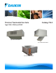
ThinLine® Horizontal Fan Coils Catalog 724-2 Type FCHC, FCHH and FCHR Exposed Horizontal Cabinet Recessed Horizontal Cabinet Concealed Horizontal Model
Table of Contents Nomenclature and Certification . . . . . . . . . . . . . . . . . 3 Unit Selection . . . . . . . . . . . . . . . . . . . . . . . . . . . . . . . 16 Features and Benefits . . . . . . . . . . . . . . . . . . . . . . . . . 4 Basic design data . . . . . . . . . . . . . . . . . . . . . . . . . 16 The ThinLine Advantage . . . . . . . . . . . . . . . . . . . . . . 5 Unit Size .
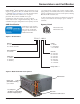
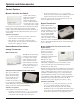
Nomenclature and Certification Nomenclature and Certification Daikin Thinline™ Horizontal Fan Coils are intended for use in single zone applications . They are available in sizes from 200 to 1200 cfm . Figure 2 and Figure 3 describe the main features of these units and can be referred to for component placement . These units are available in two-pipe configurations with one hydronic coil, with or without electric heat for main or supplemental heating .
Features and Benefits Features and Benefits Figure 3: Unit features Diverse, Flexible Valve & Piping Packages Mixing Box Modules (Automated or Manual) • Two-position fresh air damper control • Software selectable factorymounted, wired and tested • Full economizer option (with MicroTech) • Top or rear fresh air inlet • Or, factory-assembled and shipped loose • Rear or bottom return air inlet • Normally closed or open, twoposition or modulating valves Easily Removable Drain Pan & Motor Assembly • For e
Features and Benefits Features and Benefits The ThinLine Advantage ThinLine horizontal fan coils combine features most desired in a fan coil by building owners, specifying engineers and contractors alike. The result is a fan coil design that meets the needs of all three. For building owners ThinLine fan coils offer quiet and energy efficient operation. They fully comply with ASHRAE 62.1-2010 standards for high indoor air quality.
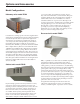
Options and Accessories Options and Accessories Model Configurations Hideaway units model FCHH open or duct collar option. Cabinets are made of heavyduty steel and insulated with ½" thick Tuf-Skin® fiber glass insulation suitable for air stream applications. Optional ¼" antimicrobial-treated closed-cell insulation is softwareselectable. Cabinets are of generous size allowing for all necessary appurtenances, including factory-installed controls and piping packages, to be covered and easily accessible.
Options and Accessories Options and Accessories Options Cabinet Color Options Discharge (supply) Air Grille . A stamped-steel supply air grilles are standard for both front and bottom discharge. Also available is a double deflection grille for front discharge units. Motor option Tamper-proof Cabinet Option This option can be factory-installed on cabinet units to prevent access to unit controls and unauthorized removal of cabinet panels. It includes torx head screws for cabinet panels.
Options and Accessories Control Options Manual 4-Position Fan Switch Several styles of the fourposition fan switch (Off, High, Med, Low) are available for unit-mount, remote- or wall-mount. The remote-mount option operates on low-voltage or line-voltage power and can be provided with a factory-mounted, low-voltage interface board, which contains (3) 24-volt relays with linevoltage contactors and terminal connections. The transformer is factory-installed and wired.
Options and Accessories T170 Thermostat with Digital Display T180 Programmable Thermostat Two thermostats are offered for remote installation only: TA170 for three-speed fan control and TB170 for staged fan operation. Both thermostats are used for OnOff control of low- or line-voltage valves with auto changeover.
Options and Accessories MicroTech Controllers ThinLine fan coils can be provided with unitmounted MicroTech controllers and multiple unit- or room-mounted sensors. MicroTech controllers can only be used with remote room sensors (described below) and not with remote thermostats. A MicroTech controller is able to operate in either a stand-alone non-communicating environment or a communicating environment.
Options and Accessories Factory Valve & Piping Packages Factory valve and piping packages are available for both two-pipe and four-pipe systems with either right or left hand connections. Four-pipe systems can be configured with the heating and cooling connections on the same or opposite sides of the unit. Packages can be either factory-installed or factory-assembled and shipped loose with the unit. All factory-assembled packages are fully leak tested.
Options and Accessories Enhanced Packages Deluxe Packages Enhanced valve and piping packages add a strainer to the Basic package supply water pipe. The strainer is attached to the supply water pipe at the coil connections. The strainer body is cast brass construction with a stainless steel mesh that is easy to remove for cleaning. Deluxe valve and piping packages add a strainer to the Premium package. The strainer is available with or without an optional draining (blow-off) valve.
Options and Accessories Control Valve Options Except for Shut-off Only packages, all valve and piping packages include control valves for controlling water flow. All Daikin control valves are factory assembled and mounted in the supply water pipe downstream of the coil . Several options are available: Two-Way Modulating Valves . Two-Way/Two-Position Valves . Three-Way Modulating Valves . Three-Way Two-Position Valves .
Options and Accessories Figure 11: Factory-installed Valve & Piping Packages (right-hand shown) Connecting or Heating ConnectingPipe PipeLocations: Locations: 2-Pipe 2-Pipe Cooling Only, Right-hand Deluxe Package shown Deluxe Package shown, see schematic (page 2) for the list of components selected for this package 5.38 3.42 ○ × REFERENCE POINT Primary Supply Front View Primary Return 0.56‡ 1.5† 7.0 20.25 B A † Overflow Connection ‡ Drain Connection ○ × REFERENCE POINT 4.
Options and Accessories Connecting Pipe Locations: 4-Pipe Cooling and Same-side Right-hand Connecting Pipe Locations: 4-Pipe Cooling & Heating, Heating Same-side, Deluxe Package shown shown, see schematic (page 2) for the list of components selected for this package Deluxe Package 10.35 7.7 ○ × REFERENCE POINT 5.38 3.42 Primary Supply Secondary Return Primary Return Secondary Supply 0.56‡ 1.5† 7.0 Front View † Overflow Connection ‡ Drain Connection 20.
Unit Selection Unit Selection To achieve an efficient fan coil system, accurate system design and proper equipment selection is necessary. Variations, limitations/control of fan coil systems, design conditions and design load calculations are not described in detail in this catalog. More detailed information may be found in the ASHRAE Guide.
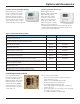
Performance Data PSC Performance Data PSC Two-Pipe Systems All performance measured on high speed tap, 115 V, at 0.05" ESP for hideaway fan coils and 0.0" ESP for cabinet fan coils. Cabinet units were tested with bottom return/front discharge configurations. Cooling performance is based on 80/67°F (27/19°C) entering air temperature, 45°F (7°C) entering chilled water temperature with a 10°F (5.5°C) temperature rise.
Performance Data PSC Performance Data PSC Four-Pipe Systems - Hot Water Preheat or Reheat (Standard or High Capacity) All performance measured on high speed tap, 115 V, at 0.05" ESP for hideaway fan coils. Cooling performance is based on 80/67°F (27/19°C) entering air temperature, 45°F (7°C) entering chilled water temperature with a 10°F (5.5°C) temperature rise.
Performance Data PSC Four-Pipe Systems - Steam Preheat or Reheat All performance measured on high speed tap, 115 V. Medium and low-speed capacities are approximately 88% and 68% respectively of the high-speed capacity. Q/ITD = MBh (kW) Saturated steam temp – Entering air temp To determine heating capacities at different entering steam pressure or entering air temperature, compute the new Inlet Temperature Differential (ITD) and multiply it by the Q/ ITD shown.
Performance Data PSC Air Volume Capacity Data . Air volumes shown in the table are measured with a dry coil at the motor speeds indicated with 115v/60/1 electrical power, with a 1" throwaway filter installed, and with a rear return/ front discharge cabinet unit configuration. Table 6: Air volume at various fan speeds PSC motors, SCFM Unit model Unit size 02 FCHH no plenum, free discharge fan 03 04 06 08 10 12 02 FCHH w/ plenum, FCHC, FCHR 03 04 06 08 10 12 20 Number of primary rows 0.
Performance Data ECM Performance Data ECM Performance Cooling and Heating – 2- and 4- Pipe Air volumes shown in the table are measured at the motor speeds indicated with 115v/60/1 electrical power, with a 1" throwaway filter installed, and with a stamped discharge grille on a horizontal cabinet unit or a discharge duct collar on a hideaway unit at approximately 0.05 inch of pressure drop.
Electrical Data Electrical Data MCA (Minimum Circuit Ampacity), MOP (Maximum Overcurrent Protection) or MFS (Maximum Fuze Size) Calculations HACR (Heating, Air-Conditioning and Refrigeration) type circuit breakers are required in the branch circuit wiring for all fan coils with electric heat. The minimum circuit ampacity (MCA) is the minimum wire size required for a field-wired product.
Physical Data Physical Data Unit Data Table 12: Physical data: coils, fans, motors and filters Primary Coil Data Face Area, ft2 (cm2) Size 02 Size 03 Size 04 Size 06 Size 08 Size 10 Size 12 1.08 (1004) 1.08 (1004) 1.43(1323) 2.11(1962) 2.46(2281) 3.14(2917) 3.83(3559) 12 (4.7) 12 (4.7) 12 (4.7) 12 (4.7) 12 (4.7) 12 (4.7) 12 (4.7) Fins/inch (cm) Connection Size 1/2" Nominal Copper (5/8" OD) Coil Dimensions 2-Row L × D × H, in (cm) 17.3 × 1.7 × 9 (43.9 × 4.4 × 22.9) 17.3 × 1.
Physical Data Physical Data Unit Dimensions Figure 12: Dimensions – Hideaway fan coil, front discharge – free return Reheat coil shown Top View 5.01 (4) Mounting Holes Secondary Drain Pan (1) ⅜" × ⅝" Control Box ⅝" O.D. Coil Connections (Typical) NOTES: 1.0 C (1) Secondary drain pan is only supplied with factory-provided piping packages 6.0 ○ × REFERENCE POINT F D 0.5 H 0.64 2.49 4.35 3.4 B 15.28 0.68 1.62 REFERENCE POINT REFERENCE POINT ○ × ○ × 9.25 6.75 8.08 9.47 9.42 9.
Physical Data Figure 13: Dimensions – Hideaway fan coil with plenum, front discharge – rear return Top View G 5.01 (4) Mounting Holes Secondary Drain Pan (1) ⅜" × ⅝" Control Box ⅝" O.D. Coil Connections (Typical) NOTES: 1.0 C (1) Secondary drain pan is only supplied with factory-provided piping packages (2) For units without mixing box 6.0 ○ × REFERENCE POINT F D 0.5 H 0.64 21.5 (2) 2.49 20.2 (2) 4.35 5.4 B 17.3 (2) 0.68 1.62 REFERENCE POINT REFERENCE POINT ○ × ○ × 9.25 9.47 8.
Physical Data Figure 14: Dimensions – Hideaway fan coil with plenum, front discharge – bottom return Top View G 5.01 0.952 Secondary Drain Pan (1) 0.952 E (4) Mounting Holes ⅜" × ⅝" Return Air Opening Control Box ⅝" O.D. Coil Connections (Typical) NOTES: 1.0 C (1) Secondary drain pan is only supplied with factory-provided piping packages 6.0 ○ × REFERENCE POINT F D 0.5 H 0.64 2.49 4.35 3.4 20.2 B 17.3 0.68 1.62 REFERENCE POINT REFERENCE POINT ○ × ○ × 9.25 6.75 8.08 9.47 11.
Physical Data Figure 15: Dimensions – Cabinet fan coil, front discharge – rear return Control Box Top View 25.0 18.0 (4) ¾" Mounting Holes RefeRence Point ○ × C.XX 2.375 D 4.5 NOTE: A 15.28 (1) Unit is shown with duct collar flanges for return and discharge openings Coil connections are 5/8" O.D. F 15.28 Front View S E S RefeRence Point ○ × 2.23 3.98 5.48 6.48 8.91 14.0 11.75 3.51 1.0 1.0 Back View RefeRence Point ○ × Side View 1.63 8.82 7.55 5.81 10.
Physical Data Figure 16: Dimensions – Cabinet fan coil, front discharge – bottom return Control Box Top View 25.0 18.0 (4) ¾" Mounting Holes RefeRence Point ○ × C.XX 2.375 D 4.5 NOTE: Coil connections are 5/8" O.D. A 15.28 (1) Unit is shown with duct collar flange for discharge opening F 15.28 RefeRence Point ○ × 2.23 3.98 5.48 6.48 8.91 11.75 14.0 3.51 Bottom View 5.81 Back View 8.82 Return S E S 2.36 7.26 9.01 10.
Physical Data Figure 17: Dimensions – Cabinet fan coil, bottom discharge – rear return Control Box Top View 35.0 28.0 (4) ¾" Mounting Holes REFERENCE POINT ○ × C.XX 2.375 D 4.5 Coil connections are 5/8" O.D. A 15.28 F 15.28 REFERENCE POINT ○ × Discharge Bottom View S 2.73 E S 2.23 7.5 Return 3.98 5.48 6.48 8.91 11.75 12.00 14.0 15.14 3.51 5.81 Back View 7.26 9.01 15.2 10.09 (4) 1" Electrical Power Knockouts (8) 2" Piping Knockouts 12.
Physical Data Figure 18: Dimensions – Cabinet fan coil, bottom discharge – bottom return Return Control Box Top View 35.0 28.0 (4) ¾" Mounting Holes REFERENCE POINT ○ × C.XX 2.375 D 4.5 Coil connections are 5/8" O.D. A 15.28 F 15.28 REFERENCE POINT ○ × 2.73 2.23 7.5 Discharge 3.98 5.48 6.48 8.91 11.75 12.00 14.0 15.14 3.51 Bottom View 5.81 Back View 15.2 8.82 S E S 10.09 (4) 1" Electrical Power Knockouts (8) 2" Piping Knockouts Return 7.26 9.01 12.
Physical Data Figure 19: Dimensions – Recessed cabinet fan coil with ceiling plate 25.0 29.5 NOTES: 2.0 typ. 7.0 7.0 X Y (1) See sheet #1 for unit dimensions (2) For installations with height restrictions below 14", use the fixed trim flange accessory 4.5 Metal or Wood Stud Frame Unit 02–03 04 Size 2.0 typ. Bottom View X 33.63 Y Material 51.64 Ceiling Multi-purpose Screw 06 08 10 12 Unit Cabinet 50.13 55.63 66.63 77.63 57.14 68.14 74.64 1/4" Gap Trim Flange 84.64 95.64 39.
Engineering Guide Specification Engineering Guide Specification PART 1: GENERAL 1.01 SECTION INCLUDES A. Horizontal Fan Coil 1.02 REFERENCES A. AFBMA 9 - Load Ratings and Fatigue Life for Ball Bearings. B. AMCA 99 - Standards Handbook. C. AMCA 210 - Laboratory Methods of Testing Fans for Rating Purposes. D. AMCA 300 - Test Code for Sound Rating Air Moving Devices. A. Maintenance Data: Include instructions for motor lubrication, where applicable, and filter replacement. 1.05 QUALIFICATIONS A.
Engineering Guide Specification Engineering Guide Specification 2.03 GENERAL CONSTRUCTION The units shall include a chassis, coil(s), fan deck with blower(s) / blower housing and motor(s). Steel parts exposed to moisture shall be galvanized and insulated to prevent condensation. The complete fan assembly shall be easily removable for service and maintenance. A quick-connect motor electric plug shall be provided. Standard chassis shall be 18 gauge galvanized steel.
Engineering Guide Specification 1.02 SUPPLY FAN A. Supply fans shall be a DWDI forward-curved type constructed of 18 ga galvanized steel for corrosion resistance. Fan housing construction shall be formed sheet metal. Fan assemblies including fan, fan housing, and motor shall be dynamically balanced by the manufacturer on all three planes at all bearing supports. Manufacturer must ensure maximum fan RPM is below the first critical speed B.
Engineering Guide Specification mounted magnetic contactor shall be supplied on all voltages. High temperature cutouts with automatic reset and one with manual reset must be provided as an integral part that de-energizes the electric heat in the event of an overheat condition. 1.01 VALVE PACKAGES A. Fan coil units shall be provided with factoryinstalled valve / piping package(s)available for the primary [and secondary]coil.
Engineering Guide Specification 1.03 CONTROLS A. [Unit shall be supplied for line-voltage controls installed by controls contractor in the field]. B. Unit shall be supplied with a factory-installed Low Voltage Interface board. 1. Low Voltage Interface board shall have three 24-volt relays with line-voltage contactors to operate the fan motor speeds. 2. Low Voltage interface board shall have terminal connections for interfacing to: PART 3: EXECUTION 2.01 INSTALLATION A.
Daikin Applied Training and Development Now that you have made an investment in modern, efficient Daikin equipment, its care should be a high priority. For training information on all Daikin HVAC products, please visit us at www.DaikinApplied.com and click on training, or call 540-248-9646 and ask for the Training Department. Warranty All Daikin equipment is sold pursuant to its standard terms and conditions of sale, including Limited Product Warranty.