Installation and Maintenance Manual Accessories for Maverick I™ Commercial Packaged Rooftop Systems IM 921 Group: Applied Systems Part Number: IM 921 Date: April 2008 Models MPS003A – 020A 3 to 20 Tons Note: This manual is a collection of various installation manuals for accessories that may be purchased separately. To print this manual with page numbers showing, choose “Documents and Markups” from the Adobe® Reader® print option settings.
Contents Carbon Dioxide Sensor. . . . . . . . . . . . . . . . . . . . . . 3 Damper (Manual) . . . . . . . . . . . . . . . . . . . . . . . . . . . 9 Damper (Motorized). . . . . . . . . . . . . . . . . . . . . . . . . 13 Disconnect Switch . . . . . . . . . . . . . . . . . . . . . . . . . 15 Dual Enthalpy Sensor . . . . . . . . . . . . . . . . . . . . . . . 17 Economizer (Convertible) . . . . . . . . . . . . . . . . . . . . 20 Economizer (Vertical) . . . . . . . . . . . . . . . . . . . . . . .
Page 3
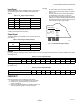
C7232A,B SENSOR AND CONTROLLER SPECIFICATIONS Models: C7232 Sensor and Controller. A stand-alone carbon dioxide (CO2) sensor with two jumper-adjustable outputs (one analog and one SPST relay). C7232A: Wall mount model. C7232B: Duct mount model. NOTE: Models are available with or without a 4-digit LCD that indicates the current CO2 concentration. Wiring Connections: C7232A: 20-gauge cable with six 8 in. leadwires. C7232B: 20-gauge cable with six 6 in. leadwires.
C7232A,B SENSOR AND CONTROLLER INSTALLATION 4. When Installing this Product... 5. 1. 2. 3. 4. Remove the screwdriver and pull the cover straight down until it meets a stop. Pull the cover straight off the subbase. Read these instructions carefully. Failure to follow them could damage the product or cause a hazardous condition. Check the ratings given in the instructions and on the product to make sure the product is suitable for your application.
C7232A,B SENSOR AND CONTROLLER Wall Mounting The C7232 Wall Mount models can be mounted using two or four screws: 1. Remove C7232 cover. 2. Mount the subbase to the wall using washers and two or four screws (not supplied) appropriate for the wall material. WIRING The factory ships the device with the output default settings shown in Tables 2 and 3. Set the jumpers and wire the device (see Table 1 and Fig. 6). CAUTION NOTE: When mounting on a junction box, see Fig. 4. 3.
C7232A,B SENSOR AND CONTROLLER Input Signal NOTES: — The C7232 Sensors have an adjustable range. These ranges are determined by the SW1 and SW2 jumper settings (see Table 2). On duct models, remove the screw holding the board in place to view jumper settings on reverse. (See Fig. 7.) The CO2 settings and the output signal settings are independent of each other.
C7232A,B SENSOR AND CONTROLLER APPENDIX IMPORTANT This page is only for models with date code prior to 0309. Pre 0309 Date Code Jumper Settings Input Signal The C7232 Sensors have an adjustable range. These ranges are determined by the SW2 and OUT1 jumper settings (see Table 6). NOTE: When choosing analog output, be sure to set the SW1 jumper to the On position. Table 6. CO2 Range Jumper Settings for models with date code prior to 0309.
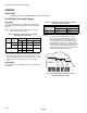
INSTRUCTIONS FOR (-)XRF-HEA1 MANUAL FRESH AIR DAMPER (-)XRX-AT01 MOTORIZED AND FRESH AIR DAMPER KIT Recognize this symbol as an indication of Important Safety Information! WARNING THESE INSTRUCTIONS ARE INTENDED AS AN AID TO QUALIFIED, LICENSED SERVICE PERSONNEL FOR PROPER INSTALLATION, ADJUSTMENT AND OPERATION OF THIS UNIT. READ THESE INSTRUCTIONS THOROUGHLY BEFORE ATTEMPTING ADJUSTMENT OR OPERATION.
IF UNIT HAS AN EXISTING MANUAL FRESH AIR DAMPER Refer to page 1. Reverse assembly procedure until damper panel assembly is removed. Assemble motorized damper assembly (see (F) below). Then reassemble fresh air damper using motorized damper assembly. IF UNIT HAS NO EXISTING MANUAL FRESH AIR DAMPER 1. Assemble motorized damper panel assembly by removing the damper slide from damper panel assembly, then attaching the (F) motorized damper to the opposite side.
DAMPER MOTOR TO ADJUST DAMPER MINIMUM POSITION 1. 2. 3. 4. Remove return air cover. Apply power to unit. Supply fan must be on. Turn potentiometer wheel on damper motor to adjust damper minimum position, 5. After successfully adjusting damper position, replace return air cover. WITH UNIT POWER ON, TURN WHEEL ON DAMPER MOTOR TO ADJUST MINIMUM POSITION RETURN AIR COVER FOR HORIZONTAL AIR FLOW INSTALLATIONS 1.
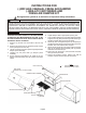
HARNESS DETAIL E# = WIRE END DESIGNATION E2 STUD #6 18 Ga. Wire E3 Female ¼ Quick Disc. E4 Male ¼ Quick Disc. Insul E6 Wire Nut Size 73B COMPONENT CODE Economizer M8405A Damper Actuator 24v PL7 Female Damper Plug PL6 Male A/C Unit Plug BLK BRN ORG WHT WIRE COLOR CODE Black BLU Blue Brown GRY Gray Orange RED Red White YEL Yellow HARNESS ENDS AT PL7 CONNECTOR & CONTACT CONFIGURATION PL7 (303917) CAP - (303902) SOCKET 0-35% Motorized Outside Air RXRX-AT01 Notes: 1. Unit wiring shown as reference only.
INSTALLATION INSTRUCTIONS MODEL RXRF - FBB1 0-35% MOTORIZED OUTSIDE AIR The 0-35% manual outside air system is designed to replace the unit duct cover. No drilling on the unit or field assembly is required. A 2-position control motor opens the intake damper when the blower is energized. The amount of air is controlled by the a slide damper on damper motor. The intake panel is fully insulated..
HAR NESS DE TAIL E# = WIRE END DES IG NA TION E2 STUD #6 18 Ga. Wire E3 Fe male 14 Quick Disc. E4 Male 14 Quick Disc. In sul E6 Wire Nut Size 73B HAR NESS STOPS AT PL5 Notes: 1. COM PO NENT CODE Economizer M847A1080 PL5 Plug PL2 Unit Plug WIRE COLOR CODE Damper Ac tua tor 24v Male Damper Fe male A/C RED BLU GRY BRN Red Blue Gray Brown 0-35% MO TOR IZED DAMPER RKKA/RJKA/RLKA 036- 072 Unit wir ing shown as ref er ence only. Rheem Manu fac tur ing 5600 Old Green wood Rd Ft.
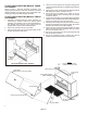
Installation Manual Disconnect Switch for Maverick I™ Units IM 904 Group: MPS Part Number: IM 904 MPS 007 to 020 ton Date: January 2008 Installation Procedure (also see diagram next page) WARNING 1. Connect the three black wires to terminals T1, T2, and T3 located on the disconnect switch. Failure to follow these instructions can result in improper installation, adjustment, service, or maintenance, and can result in fire, electrical shock, property damage, personal injury, or death.
Page 16
INSTRUCTIONS FOR DUAL ENTHALPY SENSOR UPGRADE KIT Installation Upgrade single enthalpy economizers (outdoor air enthalpy) to dual enthalpy by adding a return air enthalpy sensor and wiring it to the Honeywell model W7213A1016 Logic Module. Parts Included The sensor upgrade kit contains the following: • (1) Sensor • (1) Wiring harness • (2) No. 8-16 x ¾” PHI/PAN - TEC screws • (1) Strain relief bushing (Required for 7.5 to 25 ton units only) • (1) Sensor mounting bracket (Required for the 3 to 6 and 7.
7.5 to 25 Ton Vertical and Horizontal To mount the sensor: 1. Remove the four screws holding the return air sensor mounting plate to the damper (see Figure 3). 2. Mount the sensor to the mounting plate using the two No. 6-20 thread-forming screws (provided). WIRE HARNES ENTHALPY SENSOR MOUNTED INSIDE THE DAMPER RETURN AIR SENSOR MOUNTING PLATE Wiring 3 to 6 and 7.5 Ton Vertical To wire the sensor to the Logic Module: 1. Remove the strain relief from the damper. 2.
620 OHM RESISTOR OR C7400A1004 DUAL ENTHALPY FIELD INSTALLED OPTION Figure 5: Enthalpy Sensor Wiring Diagram MAY 24, 2006 RMIDE02 Page 19
INSTALLATION INSTRUCTIONS MODELS RXRD-MCCM3 & RXRD-MECM3 CONVERTIBLE AIRFLOW ECONOMIZERS WARNING THIS ACCESSORY IS TO BE INSTALLED BY A QUALIFIED, LICENSED SERVICE PERSON. TO AVOID UNSATISFACTORY OPERATION OR DAMAGE TO THE PRODUCT AND POSSIBLE UNSAFE CONDITIONS, INCLUDING ELECTRICAL SHOCK, REFRIGERANT LEAKAGE AND FIRE, THE INSTALLATION INSTRUCTIONS PROVIDED WITH THIS ACCESSORY MUST BE STRICTLY FOLLOWED AND THE PARTS SUPPLIED USED WITHOUT SUBSTITUTION.
FIGURE 1 RXRD-MECM3 Shown RRDX-MCCM3 Similar COIL / FILTER ACCESS 31 316 BLOWER ACCESS 3 1316 5 1132 SUPPLY COVER 82 ¼ 48 24 RETURN COVER 1 16 1 32 CONDENSATE DRAIN ¾" NPT FEMALE A0801-12 STEP 1: Immediately upon receipt, all cartons and contents should be inspected for transit damage. Units with damaged cartons should be opened immediately. If damage is found, it should be noted on the delivery papers and a damage claim filed with the last carrier.
NOTE: Units produced after August 20, 1999, have economizer connections relocated. For units produced before this date, go to STEP 6. For units produced after this date, go to STEP 7. STEP 6: These units will require an EXTENSION HARNESS (not provided) to connect the economizer to the ECONOMIZER PLUG provided on the unit.
STEP 8: Using the holes located above the return air opening on the unit attach the economizer to the REAR PANEL using the screws removed in STEP 2 (SEE FIGURE 4). FIGURE 4 WIRE TIES (3) SCREWS ECONOMIZER RAIN HOOD (FRESH AIR) ASSEMBLY STEP 9: Fasten (7) OA RAINHOOD ASSY – BOTTOM to the (5) OA RAINHOOD ASSY – LEFT SIDE and the (6) OA RAINHOOD ASSY - RIGHT SIDE.
FIGURE 5 RXRD-MECM3 Shown RRDX-MCCM3 Similar 13 11 14 12 14 ECONOMIZER RAIN HOOD - BOTTOM (BAROMETRIC DAMPER - BR) ECONOMIZER RAIN HOOD - TOP (FRESH AIR - OA) ECONOMIZER RAIN HOOD (BAROMETRIC DAMPER) ASSEMBLY STEP 13: Fasten (12) BR RAINHOOD ASSY – BOTTOM to the remaining (10) BR RAINHOOD ASSY – LEFT SIDE and the remaining (11) BR RAINHOOD ASSY – RIGHT SIDE.
NOTE: COIL NOT SHOWN FOR CLARITY HOOD EXTENSION TOP HOOD EXTENSION DIVIDER HOOD EXTENSION SIDE (10) SCREWS HOOD EXTENSION ASSEMBLY FIGURE 6 MODEL "A" 3 - 6 TON 21.750 REF 7 ½ TON 27.750 REF.
FIGURE 8 NOTE: COIL NOT SHOWN FOR CLARITY STEP 19: On downflow applications, the barometric relief hood mounts directly to the lower part of the HOOD EXTENSION opening using holes provided. On sideflow applications the barometric relief hood is attached to the return air duct. STEP 20: Mount the fresh air (upper) hood ((2) PERMANENT FILTER, (5) OA RAINHOOD ASSY – LEFT SIDE, (6) OA RAINHOOD ASSY – RIGHT SIDE, (7) OA RAINHOOD ASSY – BOTTOM, (8) OA RAINHOOD – TOP, (9) OA RAINHOOD – FILTER RETAINERS).
DIRECT MOUNT ECONOMIZER SEQUENCE OF OPERATION GENERAL This accessory economizer package is designed to save energy costs by using outdoor air for cooling and ventilation in place of mechanical cooling whenever possible. The economizer continuously monitors indoor and outdoor air conditions and compares them to a user-selected setpoint to determine if free cooling is available.
B. Range of adjustment is from 0-100% (2-10V); in most applications the minimum position is adjusted to allow 10% to 25% outside air to enter the system. C. The Outside Air Damper Minimum Position potentiometer can be adjusted at any time. D. Whenever the "G" (supply fan) signal is present, the damper will open to this minimum position unless: a. It may modulate to a greater position if overridden by the CO2 sensor (DCV). b.
C. Economizer Setpoint potentiometer can be adjusted at any time. D. The controller compares the enthalpy sensor input with the economizer setpoint to determine if free cooling is available. a. Single enthalpy strategy: If outdoor air enthalpy is lower than the setpoint, then free cooling is available. Note: The factory-installed 620-ohm resistor must be in place across terminals SR and SR+. b. Dual enthalpy strategy: If outdoor air enthalpy is lower than return air enthalpy, then free cooling is available.
TROUBLESHOOTING 1. Checkout requires a handheld multimeter, 9V battery, a 5.6k ohm ¼ watt resistor, a 1.2k ohm ¼ watt resistor, a jumper wire with ¼" quick connect terminals, and the 620 ohm resistor that is factory-installed across terminals SR+ and SR. The terminal names below reference the economizer controller. Use the following flowcharts for to diagnose unit. 2. a. Disconnect power to the unit. b. Jumper P to P1 (factory installed jumper is normally present). c.
BASIC ECONOMIZER OPERATION START Perform STEP 2 Reapply Power to the Unit Put thermostat fan setting to "CONTINUOUS FAN" Set thermostat so neither heating or cooling is called Perform STEP 3 Connect Economizer Wire Harness to Unit Check Thermostat Connections Check for 24 VAC at Unit Transformer Check Unit Wire Harness NO 24 VAC power available between terminal TR and TR1? YES Check Economizer Controller Model Number (W7213A1016) Perform STEP 2 & STEP 3 again.
HEAT PUMP OPERATION (Perform BASIC ECONOMIZER OPERATION check first) START Perform STEP 2 Perform STEP 3 Reapply Power to the Unit Put thermostat fan setting to "CONTINUOUS FAN" Turn down thermostat setting so that a call for cooling is present. Set enthalpy potentiometer on economizer controller to A (fully CCW). The "Free Cooling" LED turns on & the EXH LED turns on. If only one stage of cooling is called by the thermostat, then that stage will turn off.
Use the following graph and the multimeter to verify proper operation of the mixed air / discharge air temperature sensor. Measure the resistance (ohms) of the mixed air / discharge air temperature sensor with the multimeter. Look up the equivalent temperature on the graph. This should be the same as temperature the mixed air / discharge air sensor is detecting. If it is not, replace the mixed air /discharge air sensor. NOTES 1.
HARNESS ENDS AT PL5 COMPONENT CODE 9RT1H Mixed Air Sensor C7400A Fresh Air Sensor J2 Power Exhaust Cap MS7106K Damper Actuator 24v PL2 Female A/C Unit Plug PL5 Male Economizer Plug W7213A Logic Module Revision WIRE COLOR CODE BLK Black BLU Blue BRN Brown GRN Green GRY Gray ORG Orange RED Red TAN Tan VIO Violet WHT White YEL Yellow A Change Changed Mixed Air Sensor Date 02-23-06 CONNECTOR & CONTACT CONFIGURATION PL5 (303903) PLUG - (303901) PIN J2 (303909) CAP - (303902) SOCKET Notes: 1.
INSTALLATION INSTRUCTIONS MODELS RXRD-MDCM3 & RXRD-MFCM3 VERTICAL AIRFLOW ECONOMIZERS WARNING THIS ACCESSORY IS TO BE INSTALLED BY A QUALIFIED, LICENSED SERVICE PERSON. TO AVOID UNSATISFACTORY OPERATION OR DAMAGE TO THE PRODUCT AND POSSIBLE UNSAFE CONDITIONS, INCLUDING ELECTRICAL SHOCK, REFRIGERANT LEAKAGE AND FIRE, THE INSTALLATION INSTRUCTIONS PROVIDED WITH THIS ACCESSORY MUST BE STRICTLY FOLLOWED AND THE PARTS SUPPLIED USED WITHOUT SUBSTITUTION.
FIGURE 1 RXRD-MDCM3 Shown - RRDX-MFCM3 Similar LEAVE THESE SCREWS ENGAGED FRONT SIDE ROOF PANEL REMOVE SCREWS FROM THREE SIDES (FRONT, LEFT AND BACK) EXCEPT AS NOTED FILTERS LEFT PANEL - UPPER (REMOVE TO BE REUSED IN RAIN HOOD ASSEMBLY LEFT PANEL - LOWER (REMOVE TO BE REUSED IN RAIN HOOD ASSEMBLY RETURN COVER DOWNFLOW RETURN OPENING A1010-01 STEP 1: Immediately upon receipt, all cartons and contents should be inspected for transit damage. Units with damaged cartons should be opened immediately.
STEP 5: Secure economizer and SPOTWELD ASSY - BIRD SCREEN along bottom with six screws as shown (SEE FIGURE 2). See TABLE 1 for identification. STEP 6: Fasten EXHAUST AIR RAINHOOD - LEFT SIDE and EXHAUST AIR RAINHOOD – RIGHT SIDE to barometric relief opening (lower opening) on the economizer (SEE FIGURE 3). Fasten with six screws. See FIGURE 4 for identification of EXHAUST AIR RAINHOODS.
FIGURE 4 EXHAUST AIR RAIN HOOD (LOWER LEFT SIDE) OUTSIDE AIR RAIN HOOD (UPPER LEFT SIDE) SEAL STRIP EXHAUST AIR RAIN HOOD ASSEMBLY (BIRDSCREEN FRONT SUPPORT) END VIEW A1005-01 STEP 16: Remove the BLOWER MOTOR ACCESS PANEL (SEE FIGURE 5). FIGURE 5 STEP 17: Connect the j DISCHARGE AIR SENSOR to wires 51 and 52 located in the blower motor compartment. NOTE: Mixed air sensor should be secured with the included wire tie to avoid entanglement with the blower and direct contact with any sheet metal surfaces.
DIRECT MOUNT ECONOMIZER SEQUENCE OF OPERATION GENERAL This accessory economizer package is designed to save energy costs by using outdoor air for cooling and ventilation in place of mechanical cooling whenever possible. The economizer continuously monitors indoor and outdoor air conditions and compares them to a user-selected setpoint to determine if free cooling is available.
F. The controller compares the CO2 sensor input to the setpoint setting to determine the damper minimum position. a. If the actual CO2 level is below the setpoint, then the damper minimum position is determined by the damper minimum position potentiometer setting. b. If the actual CO 2 level rises above the setpoint, then the damper minimum position is overridden proportionally more open. c.
TROUBLESHOOTING 1. Checkout requires a handheld multimeter, 9V battery, a 5.6k ohm .25 watt resistor, a 1.2k ohm .25 watt resistor, a jumper wire with .25" quick connect terminals, and the 620 ohm resistor that is factory-installed across terminals SR+ and SR. The terminal names below reference the economizer controller. Use the following flowcharts for to diagnose unit. 2. a. Disconnect power to the unit. b. Jumper P to P1 (factory installed jumper is normally present). c.
BASIC ECONOMIZER OPERATION START Perform STEP 2 Reapply Power to the Unit Put thermostat fan setting to "CONTINUOUS FAN" Set thermostat so neither heating or cooling is called Perform STEP 3 Connect Economizer Wire Harness to Unit Check Thermostat Connections Check for 24 VAC at Unit Transformer Check Unit Wire Harness NO 24 VAC power available between terminal TR and TR1? YES Check Economizer Controller Model Number (W7213A1016) Perform STEP 2 & STEP 3 again.
HEAT PUMP OPERATION (Perform BASIC ECONOMIZER OPERATION check first) START Perform STEP 2 Perform STEP 3 Reapply Power to the Unit Put thermostat fan setting to "CONTINUOUS FAN" Turn down thermostat setting so that a call for cooling is present. Set enthalpy potentiometer on economizer controller to A (fully CCW). The "Free Cooling" LED turns on & the EXH LED turns on. If only one stage of cooling is called by the thermostat, then that stage will turn off.
Use the following graph and the multimeter to verify proper operation of the mixed air / discharge air temperature sensor. Measure the resistance (ohms) of the mixed air / discharge air temperature sensor with the multimeter. Look up the equivalent temperature on the graph. This should be the same as temperature the mixed air / discharge air sensor is detecting. If it is not, replace the mixed air /discharge air sensor. NOTES 1.
HARNESS ENDS AT PL7 COMPONENT CODE C7400A Fresh Air Sensor 9RT1H Mixed Air Sensor J2 Power Exhaust Cap MS7106K Damper Actuator 24v PL6 Male A/C Unit Plug PL7 Female Economizer Cap W7213A Logic Module Revision WIRE COLOR CODE BLK Black BLU Blue BRN Brown GRN Green GRY Gray ORG Orange RED Red TAN Tan VIO Violet WHT White YEL Yellow Change Date A Changed Mixed Air Sensor 02-23-06 B Exchanged wire 3 & 4 03-29-06 CONNECTOR & CONTACT CONFIGURATION PL7 (303917) CAP - (303902) SOCKET J2 (303909) CAP - (
--- -.------- INSTALLATION INSTRUCTIONS FOR AUXILIARY ELECTRIC HEATER KITS . A. Recognizethis symbolas an indicationof ImportantSafety Informationl IMPORTANT: TO ENSUREPROPBRINSTALLAnON ANDOPBRATION,PLBASEREADALL INSTRUCTIONSPRIOR TO ASSBMBLY, INSTALLATION,OPERATION,MAINTENANCBOR REPAIROF nus PRODUCT. AFTERUNPACKING11IB HEATERKIT, INSPECTALL PARTSFOR DAMAGBPRIORTO INSTALLATIONAND STARTUP. .
------. .ror 1I1::1U WSUUlauUU Ul 11I1 C:JCC\OC nc:aacr au" LUI1UW we instructions below: I. AU lOWvOltage wanng mUStoe roUted mto the lOWvOltage connection area and not into the power wiring or heater conCroI area. a. Removing screws as required, open heater access door and detach adjacent power entry panel. 2. For thermostat low voltage connections, see unit installation Instructions. b. Remove wires to unit contactor (Ill, 11.
Installation Manual GFCI Convenience Outlet for Maverick I™ Units IM 905 Group: MPS Part Number: IM 905 Date: January 2008 MPS007 to 020 ton Installation Procedure (also see diagram next page) WARNING Failure to follow these instructions can result in improper installation, adjustment, service, or maintenance, and can result in fire, electrical shock, property damage, personal injury, or death.
Page 49
CONVERSION KIT INDEX NATURAL GAS TO PROPANE GAS, CANADIAN HIGH ALTITUDE, AND MAIN BURNER ORIFICE CHART (-)RNL/(-)RPL/(-)KNL/(-)KPL/(-)RKA/(-)RMA/(-)RNA/(-)KKA/(-)KMA/(-)QPW (-)KNA/(-)KKB/(-)KMB/(-)KNB ROOFTOP UNITS (50 AND 60Hz MODELS) ! Recognize this symbol as an indication of Important Safety Information! ! WARNING FURNACES USED ON LP GAS MUST BE EQUIPPED WITH 100% SAFETY SHUT-OFF CONTROLS. CONVERSION WITH THE CORRECT KIT WILL MEET THIS SAFETY REQUIREMENT.
EXAMPLE Serial number on furnace rating plate: 1AD1234AAAAF12340001 CONTROL SYSTEM The first two characters in the serial number are “1A.” When the “1A” is located in Chart I, the control system in the furnace is a Honeywell VR8205 gas valve with United Tech. 1016-452 direct spark ignition control, manufactured to burn natural gas. With the model number from the rating plate, the control system from Chart I, and the type gas it presently burns, the proper conversion kit can now be selected.
USING CONVERSION KIT CHART II STEP 1) Find the appropriate control system by serial number code letters in line 2 of Chart II. STEP 2) Verify the control system listed in line 3 of Chart II by name. Also verify that the furnace actually has this type control system. STEP 3) Identify the furnace model number in lines 4 or 5 in Chart II and move across this line until it intersects the proper serial number column found in step 1. This space shows the proper conversion kit model number.
USING CONVERSION KIT CHART III The following chart should be used to verify the size of all main burner orifices for high altitude derating and natural gas to propane gas conversions. Use the furnace nameplate gas INPUT rating, the number of main burners and the altitude of the installation to select the correct natural gas or propane gas orifice size. The table is based on manifold pressures of 3.5” W.C. for natural gas and 10” W.C. for propane gas.
Page 54
Page 55
Page 56
Page 57
INSTALLATION INSTRUCTIONS MODELS RXRX-BGF03 & RXRX-BGF04 ECONOMIZER POWER EXHAUST WARNING This installation shall be carried out by a manufacturer's authorized representative, in accordance with the requirements of the manufacturer. Failure to follow instructions can result in fire or explosion, causing property damage, severe personal injury, or death. The qualified service personnel performing this work assumes responsibility for this installation.
Step 1: Remove lower barometric relief hood. Remove relief damper section from economizer or duct work. Step 2: Place relief damper section onto barometric relief damper adapter and secure with screws provided with power exhaust. Step 3: Place relief damper assembly into lower hood assembly where prepunched holes are in hood sides with screws from Step 1. Horizontal Application: Step 4: Place power exhaust over hole in duct work and secure to duct work. Adjust support legs to level power exhaust.
NOTE: COIL NOT SHOWN FOR CLARITY SECURE TO HOOD EXTENSION PREPUNCHED HOLE FOR RELIEF DAMPER FIGURE 2 COMPONENT CODE HARNESS DETAIL WIRE COLOR CODE BLK BRN GRY RED YEL Black Brown Gray Red Yellow BLU GRN ORG VIO Blue Green Orange Violet 230 Volt 1-Phase Power Exhaust for RXRX-BGF03C / RXRX-BGF04C RKKA / JKA / LKA-MA 036-090 Notes: Rooftop Systems, Inc.
HARNESS DETAIL COMPONENT CODE WIRE COLOR CODE BLK BRN GRY RED WHT Black Brown Gray Red White BLU GRN ORG VIO YEL Blue Green Orange Violet Yellow 460 Volt 1-Phase Power Exhaust for RXRX-BGF03D / RXRX-BGF04D RKKA / JKA / LKA-MA 036-090 Notes: Rooftop Systems, Inc.
INSTALLATION INSTRUCTIONS MODEL# (-)XKG SERIES ROOF CURBS This Roof Curb is built to NRCA specifications and is constructed of 18 gauge galvanized steel with a full perimeter 1" X 4" wood nailer strip. Curb height is determined by the part number as listed below. (-)XKG-CAD14 = 14 inches high (-)XKG-CAD24 = 24 inches high Step 1: Check for the correct number of parts. See list below.
INSTALLATION INSTRUCTIONS MODEL# (-)XKG SERIES ROOF CURBS HINGE PIN TAPERED END HINGE CURB SIDE Figure 4 Figure 3 Step 3: Corner Assembly: Align each curb side as shown in Figure 3. Using a hammer, drive the curb "hinge" pin down until the top of the pin is below the top of the curb as shown in Figure 4. 82 1316 82 1316 + 1 - 8 + 1 - 8 Figure 5 Step 4: After the four corners are assembled; the curb should be checked to be sure it is in "square".
INSTALLATION INSTRUCTIONS MODEL# (-)XKG SERIES ROOF CURBS DETAILS 1. Duct support inter-locks with curb. The duct support flange goes in the slot on the curb. Screw the duct support to the curb. The (-)XKG can now have the duct support and the insulated pans installed, unless a transition (RXMC-CB03 or CB04) is to be installed. If this is the case follow transition instruction from this point. Step 5: Place the duct support (C) on the curb, making sure that it is in the right location. See "DETAIL #1".
INSTALLATION INSTRUCTIONS MODEL# (-)XKG SERIES ROOF CURBS TYPICAL INSTALLATION (4) CORNERS OF UNIT UNIT BASEPAN INSTALLATION REQUIRES FIELD DRILLING TIE DOWN BRACKET Step 10: To secure unit to curb, position unit on curb. Using four of the #10 x ½" self drilling screws, attach the tie down bracket furnished, as shown in detail. Recheck all joints to assure watertightness.
INSTALLATION INSTRUCTIONS MODEL# (-)XKG SERIES ROOF CURBS This Roof Curb is built to NRCA specifications and is constructed of 18 gauge galvanized steel with a full perimeter 1" X 4" wood nailer strip. Curb height is determined by the part number as listed below. (-)XKG-CAE14 = 14 inches high (-)XKG-CAE24 = 24 inches high Step 1: Check for the correct number of parts. See list below.
INSTALLATION INSTRUCTIONS MODEL# (-)XKG SERIES ROOF CURBS HINGE PIN TAPERED END HINGE CURB SIDE Figure 4 Figure 3 Step 3: Corner Assembly: Align each curb side as shown in Figure 3. Using a hammer, drive the curb "hinge" pin down until the top of the pin is below the top of the curb as shown in Figure 4. 103 716 103 716 + 1 - 8 + 1 - 8 Figure 5 Step 4: After the four corners are assembled; the curb should be checked to be sure it is in "square".
INSTALLATION INSTRUCTIONS MODEL# (-)XKG SERIES ROOF CURBS DETAILS 1. Duct support interlocks with curb. The duct support flange goes in the slot on the curb. Screw the duct support to the curb. The RXKG can now have the duct support installed, if a transition (RXMC-C***) is to be installed. If this is the case follow transition instruction from this point. Step 5: Place both duct supports (D) on the curb, making sure that it is in the right location. See "DETAIL #1".
INSTALLATION INSTRUCTIONS MODEL# (-)XKG SERIES ROOF CURBS TYPICAL INSTALLATION (4) CORNERS OF UNIT UNIT BASEPAN INSTALLATION REQUIRES FIELD DRILLING TIE DOWN BRACKET Step 9: To secure unit to curb, position unit on curb. Using four of the #10 x ½" self drilling screws, attach the tie down bracket furnished, as shown in detail. Recheck all joints to assure watertightness.
INSTALLATION INSTRUCTIONS MODEL# (-)XKG SERIES ROOF CURBS This Roof Curb is built to NRCA specifications and is constructed of 16 gauge galvanized steel with a full perimeter 1" X 4" wood nailer strip. Curb height is determined by the part number as listed below. (-)XKG-CAF14 = 14 inches high Figure 1 Step 1: Check for the correct number of parts. See list below.
INSTALLATION INSTRUCTIONS MODEL# (-)XKG SERIES ROOF CURBS HINGE PIN TAPERED END HINGE CURB SIDE Figure 4 Figure 3 Step 3: Corner Assembly: Align each curb side as shown in Figure 3. Using a hammer, drive the curb "hinge" pin down until the top of the pin is below the top of the curb as shown in Figure 4. 150 1116 150 1116 + 1 - 8 + 1 - 8 Figure 5 Step 4: After the four corners and middle hinges are assembled; the curb should be checked to be sure it is in "square".
INSTALLATION INSTRUCTIONS MODEL# (-)XKG SERIES ROOF CURBS DETAILS 1. The RXKG can now have the duct support installed, if a transition (RXMC-C***) is to be installed. If this is the case follow transition instruction from this point. Duct support interlocks with curb. 2. Duct support interlocks with pan or other duct support. Step 5: Place all three duct supports (E) on the curb, making sure that it is in the right location. See "DETAIL #1".
INSTALLATION INSTRUCTIONS MODEL# (-)XKG SERIES ROOF CURBS TYPICAL INSTALLATION (4) CORNERS OF UNIT UNIT BASEPAN INSTALLATION REQUIRES FIELD DRILLING TIE DOWN BRACKET Step 9: To secure unit to curb, position unit on curb. Using four of the #10 x ½" self drilling screws, attach the tie down bracket furnished, as shown in detail. Recheck all joints to assure watertightness.
Installation Manual Smoke Detector IM: 908 Group: MPS Date: January 2008 Supersedes: None The MQuay smoke detector is designed specifically for applications where standard external mount detectors cannot be utilized, such as air shafts, plenum spaces, or applications requiring extremely low, or no air velocity. The detector provides early detection of smoke and combustion present in the air of a duct supply, return, or both, in commercial, residential, and industrial applications.
Specifications 1 The smoke detector can be mounted in the duct or in the Table 1: Unit Specifications Power Requirements 60 Hz Alarm Current 24 V (ac) – 139 mA 24 V (dc) – 48 mA 115 V (ac) – 34 mA 230 V (ac) – 20 mA Unit Ratings Alarm Contacts: 1 set form “C” rated at 10 A @ 115 V (ac) resistive 1 form “A” rated at 2 A Trouble Contact: 1 set form “B” rated at 10 A @ 115 V (ac) resistive Air Velocity 0 to 3000 ft/min.
Page 76
Page 77
Page 78
Page 79
Page 80
Page 81
Engineering Data ED: 9043 Group: MPS Date: January 2008 Supersedes: None 3 Heat, 2 Cool Thermostat for Maverick I™ Units Single Stage, Multi-Stage, and Heat Pump Applications The commercial setback digital thermostat uses microcomputer technology to provide precise time and temperature control. This thermostat offers the flexibility to design heating and cooling programs that fit building needs.
Features Specifications The T170 thermostat can enhance your HVAC system by offering you the following performance features. Table 1: Thermostat specifications Electrical Rating Single Stage: mV to 30 V (ac), NEC Class II, 50/60 Hz or DC Electrical Rating Staging: 20 to 30 V (ac), NEC Class II Terminal Load: 5 A per terminal, 2.5 A max.
Engineering Data ED: 9045 Group: MPS Date: January 2008 Supersedes: None Thermostat Guard for Maverick I™ Units All Thermostat Types Features The thermostat guard can enhance your HVAC system by offering you the following features: • Accepts all thermostat types • Each model is furnished with one key and can be mounted vertically or horizontally • Clear plastic models for applications that need the thermostat visible • Furnished with a ring and/or solid wall mounting plate © 2008 McQuay International P
Engineering Data ED: 9044 Group: MPS Date: January 2008 Supersedes: None Remote Sensor for Maverick I™ Units Indoor and Outdoor Sensor for Digital Thermostats Features The remote sensor can enhance your HVAC system by offering you the following performance features: • Digital signal output provides superior temperature control, even over long wire runs • No temperature variance caused by wire resistance • Choice of styling, indoor models are interchangeable • Perfect for securing the thermostat in on are
McQuay Training and Development Now that you have made an investment in modern, efficient McQuay equipment, its care should be a high priority. For training information on all McQuay HVAC products, please visit us at www.mcquay.com and click on training, or call 540-248-9646 and ask for the Training Department. Warranty All McQuay equipment is sold pursuant to its standard terms and conditions of sale, including Limited Product Warranty. Consult your local McQuay Representative for warranty details.