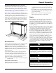
Installation and Maintenance Manual ThinLine 3G Vertical Fan Coils Type FCVC, FCVH, FCVS and FCWC Vertical Design 200 to 1200 cfm IM 980-1 Model FCVC Model FCVS © 2011 Daikin IM 980-1 Group: Applied Air Systems Part Number: 910150486 Date: May 2011
Table of Contents IM 980-1 . . . . . . . . . . . . . . . . . . . . . . . . . . . . . . . . . . . . . . . . . .3 IM 1014 - MTA/B 155 Electronic Thermostats . . . . . . . . . .45 General Information . . . . . . . . . . . . . . . . . . . . . . . . . . . . . . . . . . . . 3 Receiving and Storage . . . . . . . . . . . . . . . . . . . . . . . . . . . . . . . . . . 4 Pre-Installation . . . . . . . . . . . . . . . . . . . . . . . . . . . . . . . . . . . . . . . . 4 Installation . . . . . . . . . . . . . . . . .
General Information General Information Thinline™ 3G Vertical Fan Coils are intended for use in single zone applications. They are available in sizes from 200 to 1200 cfm. Figure 2 describes the main features of these units and can be refered to for component placement. These units are available in two-pipe configurations with one hydronic coil, with or without electric heat. They are also available in fourpipe configurations with one primary coil and a secondary reheat or preheat coil.
General Information Receiving and Storage Upon receipt of the equipment, check carton for visible damage. Make a notation on the shipper’s delivery ticket before signing. If there is any evidence of rough handling, immediately open the cartons to check for concealed damage. If any damage is found, notify the carrier within 48 hours to establish your claim and request their inspection and a report. The Warranty Claims Department should then be contacted. installed in the correct location.
General Information Recommended Maintenance Clearance Cabinet units have removable front and side panels for easy access to components for service and maintenance. The fan assembly and main drain pan are easily removable from the front for cleaning. See Accessing/removing the main drain pan and motor assembly‚ page 19 for more information. Figure 4 shows recommended maintenance clearances: 0.5 inches (13 mm) on either side and 10 inches (254 mm) in front.
Installation Installation Uncrating and Inspecting the Unit Figure 5: Cabinet Side Panel Removal 1 Carefully remove the packaging, remaining alert to any signs of shipping damage. Be careful not to discard components that may be included with the packaging. 2 If the unit is damaged, file a claim with the carrier. Notify the local Daikin representative immediately.
Installation select the correct fasteners for each unit to meet local codes. At location(s) where no stud is present, secure with a Toggle bolt or equivalent. Note: Use a minimum of two fasteners on each side to secure the unit (field supplied). packages with unions, o-rings are included. When soldering near unions, remove the o-rings before heating. Figure 7: Protect Components From Overheating 12 On cabinet units, reinstall the side/quarter panels in reverse order as performed in step 4.
Installation 11 Do not connect a unit to the supply and return piping until the water system has been cleaned and flushed completely. After this is done, the initial connection should have all valves wide open in preparation for water system flushing. 12 Condensate piping can be steel, copper, or PVC. A means of disconnection must be furnished to facilitate fan section removal.
Installation main supply line and the fan coil unit. These can be furnished as part of a factory-installed valve & piping package or they can be installed in the field. The balancing valve installed on the return line is used to adjust the water flow to provide the best performance. Figure 10: Changeover switch & sensor attachment Condensate Drain Connection 1 Connect a copper or plastic pipe to the 7/8 inch copper pipe on the secondary drain pan.
Installation 1 Vent the vacuum breaker line to atmosphere or connect it into the return main at the discharge side of the steam trap. 2 Pitch all steam supply and return mains down a minimum of one inch per ten feet in the direction of flow. Electrical Connections Installation and maintenance must be performed only by qualified personnel who are familiar with local codes and regulations, and are experienced with this type of equipment. DANGER 3 Do not drain the steam mains or takeoff through the coils.
Installation Install a strain relief and pass the wires through the strain relief into the junction box. Make the connections and reinstall the junction box cover. Note: Voltages listed are to show voltage range. However, units operating with overvoltage and undervoltage for extended periods of time will experience premature component failure. Electrical Data The wiring diagram for the unit is attached to the inside of the corner panel on cabinet units.
Installation 3 Fill the system at the city water makeup connection with all air vents open. After filling, close all air vents. 4 Start the main circulator with the pressure reducing valve open. 5 Check vents in sequence to bleed off any trapped air, ensuring circulation through all components of the system. 6 While circulating water, check and repair any leaks in the unit and surrounding piping. CAUTION Units must be checked for water leaks upon initial water system startup.
Operation and Maintenance Operation and Maintenance Controls A wide variety of control options are available for ThinLine 3G Vertical Fan Coils, both unit-mounted and remotemounted. This section provides a brief overview of these options and their operation. For more complete information, contact your Daikin representative. Manual 4-Position Fan Switch This four-position fan switch (Off, High, Med, Low) option, shown at the right, is available remote-mounted.
Operation and Maintenance • On-Off fan and On-Off valve cycle operation: The thermostat cycles the fan from the manually selected fan speed to off and it cycles the valves on and off. Heating and cooling outputs for the MT158 are individually configurable for three-wire floating control valves or On/Off valves in the Normally Open or Normally Closed modes. When the system switch is in the OFF position, the fan coil system including the fan is shut off.
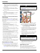
Operation and Maintenance Low-Voltage (LV) Interface Board The low-voltage interface board is used with any remote (wall mounted) Daikin thermostat or control. It can also be used in conjunction with a controller of a building automation system (BAS) control where low voltage is needed to operate the fan coil. It is located in the control box for the unit (see Figure 11, page 10). The LV interface board includes: See Figure 18 for a list of connecting points to the board.
Operation and Maintenance Accessories Fresh Air Damper The fresh air damper kit provides up to 25% outside air to the unit heater. It consists of an intake with damper blade and insect screen. The damper may be manually controlled through the return air opening or with an optional field-installed damper motor. For detailed installation information, refer to page 37. Fresh Air Damper Motor Kit (Low Voltage) This damper motor kit is for field installation with the fresh air damper kit.
Operation and Maintenance Leveling Legs Option Electric Heat Over-Temp Reset Button Field or factory-installed kits are available with 0” to 1" adjustment for positive leveling of floor-mounted units. The elecric heat options comes with two over-temperature switches. The first resets automatically when the overtemperature condition no longer exists. The second, backup switch must be reset manually.
Operation and Maintenance Key-lock Access Door Kit The key-lock access door kit (see Figure 26) can be installed on ThinLine 3G cabinet units to prevent access to unit controls. For detailed installation information, refer to page 43. Figure 26: Key-Lock Access Door Kit 4 Remove the filter from under the unit. To install a new filter: 1 Slide the filter under the unit and tilt its rear 0edge upward and into the pocket at the rear of the filter housing.
Operation and Maintenance Accessing/removing the main drain pan and motor assembly Figure 29: Motor Connector Location The main drain pan is housed in the top of the unit’s fan deck. Both the fan deck and the main condensate drain pan are easily removed for access and cleaning as follows. 1 Disconnect electrical power to the unit. 2 Remove the two screws that attach the center panel of the unit to the base ( see Figure 5, page 6). 3 Lift the center panel upward and off the unit.
Physical Data Physical Data Unit Data Table 1: Unit Data 02 03 04 06 08 10 12 0.74 (685) 1.08 (1004) 1.43 (1323) 2.11 (1962) 2.46 (2281) 3.14 (2917) 3.83 (3559) 12 [4.7] 12 [4.7] 12 [4.7] 12 [4.7] Primary Coil Data Face Area, ft2 (cm2) Fins/inch (cm) Coil Connection 12 [4.7] 12 [4.7] 12 [4.7] 1/2" Nominal copper female (5/8" OD) Coil Dimensions 2-Row 11.8 x 1.7 x 9 17.3 x 1.7 x 9 22.8 x 1.7 x 9 33.8 x 1.7 x 9 39.3x 1.7 x 9 50.2 x 1.7 x 9 61.3 x 1.7 x 9 L x D x H, in (cm) (30.0x4.4x22.
Physical Data Unit Dimensions Figure 30: Dimensions: Flat Top Fan Coils 3.6 90.3 TOP VIEW ELECTRICAL CONTROL ACCESS DOOR C ELECTRIC HEAT OPTION PREHEAT OPTION REHEAT OPTION GG EE HH 1.3 33.8 E DISCHARGE GRILL FF EE A CC DD DD DD CC BB BB AA FRONT VIEW B AA BB AA EE HH CC PRIMARY ELECTRIC HEAT F GG GG 8.8 [224] FF 8.8 [224] OPTIONAL DISCONNECT SWITCH REHEAT PRIMARY 6.1 154 PRIMARY PREHEAT BACK VIEW 8.9 227 1.0 24.7 17.6 15.7 [447] [399] J K 3.4 [86] 4.6 [117] 9.
Physical Data Figure 31: Dimensions: Slope Top Fan Coils 3.7 95.1 TOP VIEW DISCHARGE GRILL ELECTRIC CONTROL ACCESS DOOR ELECTRIC HEAT OPTION PREHEAT OPTION REHEAT OPTION GG EE C E FF EE 1.9 47.4 A HH FRONT VIEW CC DD DD B DD CC BB AA BB AA AA CC BB HH GG PRIMARY ELECTRIC HEAT F EE FF 8.8 [224] GG PRIMARY 8.8 [224] ELECTRICAL CONTROL BOX OPTIONAL DISCONNECT SWITCH REHEAT 6.1 154 PRIMARY PREHEAT BACK VIEW 17.6 [447] 15.7 [399] 8.9 227 .9 23.1 J 5 [127] 3.4 [86] 2.
Physical Data Figure 32: Dimensions: Hideaway, Front-Discharge Fan Coils TOP VIEW A C PREHEAT OPTION ELECTRIC HEAT OPTION REHEAT OPTION FRONT DISCHARGE FF GG EE 1.0 26.6 E HH 5.4 138.2 CC DD B B DD CC BB AA BB AA HH G PRIMARY ELECTRIC CONTROL BOX F EE GG FF PRIMARY FRONT VIEW H 0.6 [15.9] 0.6 [15.9] PREHEAT OPTIONAL DISCONNECT SWITCH REHEAT 6.1 154 PRIMARY ELECTRIC HEAT 8.9 227 BACK VIEW H G J 5 127 4.6 117 9.3 236 S02 Dimension Unit Width S03 2.
Physical Data Figure 33: Dimensions: Hideaway, Top-Discharge Fan Coils 3.5 89.6 TOP VIEW A PREHEAT OPTION ELECTRIC HEAT OPTION GG 1.3 32.9 GG 1.3 32.9 FF EE EE B DD TOP DISCHARGE ELECTRIC CONTROL BOX CC DD BB DD B AA B FRONT VIEW AA BB BB AA HH OPTIONAL DISCONNECT SWITCH F EE FF PRIMARY E 1.3 32.9 HH CC CC 4.8 120.7 REHEAT OPTION GG T PRIMARY 6.1 154 PRIMARY ELECTRIC HEAT T REHEAT PREHEAT 8.9 227 BACK VIEW G H J 5 127 4.6 117 9.
Physical Data Factory-Installed Valve & Piping Packages See catalog CAT 722-1 for detailed descriptions of piping packages.
Wiring Diagrams Wiring Diagrams Figure 35: Fan Coil Wiring Diagram - Typical with solid-state thermostat Note: All field installed conductors should have an insulation rating of 300 volts or greater.
Wiring Diagrams Figure 36: Fan Coil Wiring Diagram - Typical with unit-mounted three-speed fan switch Note: All field installed conductors should have an insulation rating of 300 volts or greater.
Wiring Diagrams Figure 37: Fan Coil Wiring Diagram - Typical with electric heat and low-voltage interface board Note: All field installed conductors should have an insulation rating of 300 volts or greater.
Model Number Description Model Number Description Table 1: Model Number Description: Fields 1 - 21 Field Code 1 2 FC VC 3 4 5 6 7 8 9 10 1 02 A A G M Y YY W 1 Unit Type 11 12 13 14 15 16 17 18 19 20 21 3 12 R F T YY 12 • 2 = 2 row • FH = cabinet unit heater • 3 = 3 row 2 Product Identifier • 4 = 4 row • VH = vertical hideaway • VS = vertical cabinet, slope top • 12 = 12 fins per inch 14 Primary Coil Connection Hand • L = left hand 3 Design Series • R = right hand 15 Pri
Model Number Description Table 2: Model Number Description: Fields 21 - 41 Field 22 23 24 25 26 27 28 29 30 31 32 Code YY W1 12 R F T Y 000 Y 22 Not currently used • YY = none 23 Reheat Coil Type P PSC S 3 Q Y MR Y D Y R 30 Not currently used • YY = none 31 Drain Pan Material • W1 = 1-row water • P = plastic, non-corrosive • S1 = 1-row steam • S = stainless steel • YY = none 24 Reheat Coil Fins Per Inch • 12 = 12 fins per inch 25 Reheat Coil Connection Hand • L = left hand • R = right
Model Number Description Table 3: Model Number Description: Fields 43-59 48 49 50 Field 42 43 44 45 46 47 Code Y Y Y RL MOR Y 3MOU YYYY 3MOU 42 Network Communication Card 51 52 53 54 55 56 Y Y C Y Y Y Table 4: Model Number Detail: Coil Valve Fields 49, 50, 51 3OMU • Y = none 43 Changeover Type • Y = none • A = auto Coil Valve Type Y = none 2 = two-way 3 = three way • M = manual • U = user selectable 44 Programmability • Y = none 45 Setpoint Adjustment • YY = none • UL = unit-mounted, +/
Model Number Description Table 5: Model Number Description: Fields 57 - 72 Field 57 58 59 60 61 62 63 64 65 66 67 68 69 70 71 72 Code Y Y Y Y S 18 P 57 Filter Status Sensor I 00 S 00 00 30F TA FR 1 67 Left Hand End Pocket Extension • Y = None • 00 = None • X = special • 04 = 4 Inch Extended Length 58 Fan Status Sensor • Y = None • X = special 59 Future Control Function • Y = None 60 Future Control Function • Y = None 61 Cabinet Style • 08 = 8 inch Extended Length 68 Right Hand End Poc
Model Number Description Table 6: Model Number Description: Fields 73 - 78 73 74 75 76 77 78 Field Code YYY Y A S Y 1 73 Special Options • YYY = none 74 Reserved for future use • Y = none 75 Agency Listing • A = ETL, CETL, ARI • R = ETL, CSA • X = special • Y = none 76 Packaging • S = Standard • T = palletized based on tagging and by floor Daikin IM 980-1 77 Extended Warranty • Y = none (standard warranty) • 1 = 1 year Extended component warranty (30 month from shipment or 24 month from instal
This page intentionally left blank.
IM 1121 - Hideaway Unit Discharge Conversion Kit Installation and Maintenance Manual ThinLine™ 3G Hideaway Unit Discharge Conversion Kit Safety Information WARNING Group: Applied Air Systems Part Number: 910118016 Date: March 2011 Table 1: Discharge Conversion Kits Unit Size Part Number Quantity 02 03 04 06 08 10 12 910113221 910113222 910113223 910113224 910113225 910112579 910113226 1 1 1 1 1 1 1 The installation of this equipment shall be in accordance with the regulations of authorities having
Figure 1: Removing the Discharge Duct Collar and Front Block-off Plate Discharge Duct Collar Front Block-Off Plate Figure 2: Attaching the Top Block-Off Plate and Short Front Panel Top Block-Off Plate Short Front Panel 36 Daikin IM 1121
IM 1023 - Fresh Air Damper Kit Installation and Maintenance Manual Fresh Air Damper Kit for ThinLine™ 3G Vertical Fan Coils The fresh air damper kit provides up to 25% outside air to the fan coil. It consists of an intake with damper blade and insect screen. The damper may be manually controlled through the return air opening or with an optional field-installed damper motor.
Operation To open the damper, reach under the unit and pull the damper handle toward you. To close, push the damper away from you. See Figure 4. Figure 5: Adjusting Damper Tension To adjust damper tension, loosen or tighten nuts on each end of damper axis.
IM 1028 - Fresh Air Damper Motor Kit Installation and Maintenance Manual Fresh Air Damper Motor Kit for ThinLine™ 3G Vertical Fan Coils This damper motor kit is set up for field installation with the corresponding fresh air damper kit for ThinLine 3G fan coils. The damper kit must be ordered separately. The damper motor is always mounted on the same end as the unit control box. The unit control box is always mounted on the opposite side of the primary coil connections.
4 Install the coupling on the end of the damper pivot rod closest to the unit control box With the damper blade in the closed (up) position, secure the coupling by tightening the setscrew with the setscrew facing the front of the unit. Note: Suggestion: flatten the threads of the damper pivot rod where it contacts the setscrew to prevent the setscrew from slipping. 5 Attach the damper motor to the mounting bracket with two #8-32 x 3/8" screws.
IM 1024 - Cabinet Rear Extension Kit Installation and Maintenance Manual Cabinet Rear Extension Kit for ThinLine™ 3G Vertical Fan Coils and Unit Heaters IM 1024 Group: Applied Air Systems Part Number: 910102148 Date: August 2009 The field-installed cabinet rear extension option may be utilized to place the fan coil farther out from the wall than the standard unit allows. Installation Instructions Note: This option is not designed to be an air duct or outside air plenum.
3 Attach Subbase Extensions to the Right and Left Chassis Support Panels using 1 screw in each. See Figure 2. 4 Attach the Top Cabinet Panel to the Right and Left Cabinet Side Panels using 4 screws (2 on each side). See Figure 3. 7 Attach extension to fan coil unit as follows (see Figure 5): a Attach the Subbase Extensions to the left and right subbases on the unit using 4 screws. b Attach the Left and Right Chassis Support Panels to the left and right coil panels on the fan coil unit using 6 screws.
IM 1021 - Key-Lock Access Door Kit Installation and Maintenance Manual Key-Lock Access Door for ThinLine™ 3G Vertical Fan Coils The key-lock access door kit can be installed on ThinLine 3G cabinet units to prevent access to unit controls. It is installed as follows. Group: Applied Air Systems Part Number: 668115705 Date: August 2009 3 Remove the hinge pins from the old control door by either re-rounding the flattened pin ends with a needlenose pliers or drilling out the pins with a 5/32” drill bit.
This page intentionally left blank.
IM 1014 - MTA/B 155 Electronic Thermostats Installation and Maintenance Manual IM 1014 MT 155 Thermostat Group: Applied Air Systems Part Number: 910102989 Date: August 2009 Installation Figure 1: Removing Jumper JP-1 INSTALL COVER LOCKING SCREW DANGER READ THESE INSTRUCTIONS CAREFULLY BEFORE ATTEMPTING TO INSTALL, OPERATE OR SERVICE THIS THERMOSTAT. To avoid electrical shock or damage to equipment, disconnect power before installing or servicing.
for fan continuous operation or is dependant upon connection to the fan supply input . When internally wired for fan continuous operation, the fan will be off when the system switch is off. When dependant upon external connections the fan may not be off with the system switch in the off position. The fan supply input is switched to fan speed outputs (HI MED - LO). 7 Observe electrical ratings. Thermostatic outputs are pilot duty only.
IM 1089 - Field Installation of MT155 Thermostats Installation and Maintenance Manual Field installation of Thermostat (MTA155 or MTB155) and 24V valve packages on Vertical Thinline 3G fan coil units with factory-installed Low Voltage Interface Board General DANGER READ THESE INSTRUCTIONS CAREFULLY BEFORE ATTEMPTING TO INSTALL, OPERATE OR SERVICE THIS THERMOSTAT. Failure to observe safety information and comply with instructions could result in PERSONAL INJURY, DEATH AND/ OR PROPERTY DAMAGE.
Figure 2: Low Voltage Interface Board shown with all additional support options Line Voltage Hi-Med-Lo Fan motor control FA Clg. 24vac valve actuators inputs Htg. 24vac valve actuators inputs Room air or return air temperature sensor Wiring Harness Clg. 24vac valve actuators – with quick connects t Pipe sensor or ACO switch Condensate overflow sensor output Remote thermostat 24 VAC power Htg.
Figure 4: Thermostat TB155 autochangeover to be used with On-Off 24V valve packages, SPDT ACO and unit-mounted Low Voltage Interface Board Figure 5: Automatic changeover switch (SPDT ACO Kit P/N 039398600) • 10K Return Air Sensor - PN 107345501 for unit-mounted applications only (for wall-mounted applications the sensor is imbedded with the thermostat) Step 1: Installing valve packages • Solder the appropriate inlet and outlet CW pipe connections from the valve package to the coil connections.
This page intentionally left blank.
Installation and Maintenance Manual IM 1015 MTA 158 Microprocessor Thermostat On/Off Controller IM 1015 - MT 158 and MT 168 Digital Thermostats Installation Group: Applied Air Systems Part Number: 910102990 Date: August 2009 READ THESE INSTRUCTIONS CAREFULLY BEFORE ATTEMPTING TO INSTALL, OPERATE OR SERVICE THIS THERMOSTAT. Failure to observe safety information and comply with instructions could result in PERSONAL INJURY, DEATH AND/ OR PROPERTY DAMAGE.
Thermostat Operation These thermostats are designed to control On-Off, N.O. and N.C. valves, relays and Erie® three wire floating valves. These units may include a fan switch with one or more fan speed selections. Mode Button Operation OFF: All thermostat outputs are off, fan is still operational if connected to manual fan speed switch. AUTO: The thermostat automatically selects heating or cooling mode depending on the set point and room temperature.
Figure 3: Circuit Board Jumpers 2 3 4 5 6 AUTO J P4 15 16 17 5 6 7 J P1 1 2 3 4 10 11 12 13 1 ON DIP S WIT C H Table 3: Circuit Board Jumper Configuration Jumper Designation Jumper Installed ON Jumper Removed JP1 Local Sensing Remote Sensing JP4 2 Pipe System* 4 Pipe System Application Notes 1 When no pipe sensor is used the main output controls cooling and the secondary output controls heating.
This page intentionally left blank.
IM 1016-1 - MTB 158 Microprocessor Thermostats Installation and Maintenance Manual IM 1016-1 MTB 158 Microprocessor Thermostat On/Off and 3-Wire Controller Group: Applied Air Systems Part Number: 910102991 Date: November 2010 CAUTION DANGER Failure to observe safety information and comply with instructions could result in PERSONAL INJURY, DEATH AND/ OR PROPERTY DAMAGE. To avoid electrical shock or damage to equipment, disconnect power before installing or servicing.
2 For wall installations, mount the thermostat on an inside wall approximately 5 feet above the floor. The location should provide circulation at average room temperature. Avoid direct sunlight or sources of hot or cold air in the room or wall. 3 Remove the cover. Mount thermostat base assembly to the outlet box using the screws provided, tighten the screws evenly but do not over tighten. Connect wires as shown in the appropriate wiring diagram for your thermostat style.
Application Notes Figure 3: Circuit Board Jumpers 2 3 4 5 6 DIP S WIT C H cooling and the secondary output controls heating. AUTO input for water system operation and in the main duct system for forced air operation. J P4 10 11 12 13 15 16 17 1 2 3 4 2 The pipe sensor should be mounted on the main coil 1 ON 1 When no pipe sensor is used the main output controls 5 6 7 3 The set point and operating mode will be retained on a J P1 loss of power.
This page intentionally left blank.
IM 1017 - MT 168 0-10Vdc/4020mA Thermostats Installation and Maintenance Manual IM 1017 MT 168 0-10 VDC/4-20mA Thermostat Group: Applied Air Systems Part Number: 910102992 Date: August 2009 Installation Figure 1: Mounting DANGER READ THESE INSTRUCTIONS CAREFULLY BEFORE ATTEMPTING TO INSTALL, OPERATE OR SERVICE THIS THERMOSTAT. Failure to observe safety information and comply with instructions could result in PERSONAL INJURY, DEATH AND/ OR PROPERTY DAMAGE.
5 Connecting a jumper between terminals 16 and 17 will disable the secondary output and change the main output to heat mode. 6 Connection of a 24 VAC set-back signal will force the control into unoccupied mode (see diagram). Pressing an arrow key or the mode buttons on the thermostat cover will disable the setback input for one hour. 7 Remove the LCD plastic protective film to complete the installation. Reinstall the cover assembly. Install cover locking screw provided.
Table 3: Dip Switch Configuration Switch Closed On* Open Off 1 Not Used Not Used 2 Staged Heat 3°F Diff. (Term. 13) Aux. Heat No Diff. (Term. 13) 3 F Display C Display 4 Main & Sec. Outputs 0-10 VOC (Term. 10 & 11) requires JP4 & JP5 Main & Sec. Outputs 4-20 mA (Term. 10 & 11) Remove JP4 & JP5 5 Operating Position Not Used 6 Setback= 90°F & 50°F Setback = 85°F & 60°F Note: * On is with the dip switch handle to the right. See diagram below.
This page intentionally left blank.
IM 846 - MT 170 Thermostats Installation and Maintenance Manual T170 Thermostat IM-846 Group: Fan Coil Part Number: 910102993 Date: July 2006 24 VAC/120–277 VAC 3-Speed Fan Control (Continuous or Cycling) or Staged Fan Control US © 2006 Daikin 800-432-1342 www.DaikinApplied.
Table of Contents Table of Contents Installation Instructions . . . . . . . . . . . . . . . . . . . . . . 3 Thermostat Model and Part Number . . . . . . . . . . . . . . . . . . . . . . . . 3 Optional Occupancy Detection Sensors/Kits. . . . . . . . . . . . . . . . . . 3 Mounting and Wiring the Thermostat . . . . . . . . . . . . . . . . . . . . . . . 3 Operation. . . . . . . . . . . . . . . . . . . . . . . . . . . . . . . . . . 5 Thermostat Button Operation . . . . . . . . . . . . . . . . . . . . . . . . .
Installation Instructions Installation Instructions Mounting and Wiring the Thermostat WARNING • BEFORE ATTEMPTING TO INSTALL, OPERATE, OR SERVICE THIS THERMOSTAT, CAREFULLY READ THESE INSTRUCTIONS. • Failure to observe safety information and comply with instructions could result in PERSONAL INJURY, DEATH, AND/OR PROPERTY DAMAGE. • To avoid potential fire and/or explosion, do not use in potentially flammable or explosive atmospheres. • Retain these instructions for future reference.
Installation Instructions 5 On the circuit board, set the voltage selection switch Figure 3: Wiring diagram (Figure 2) to the appropriate voltage for the application Setback input/door switch White/Black Note: The circuit board is shipped with the voltage selection switch in the 110-227 V position. For 24 VAC use, the switch must be in the 24 V position. Before applying power, the voltage selection switch must be in the appropriate position.
Operation Operation Thermostat Button Operation UP/Down Arrow Button Operation The thermostat interface (Figure 4) contains buttons for use in navigating to accompanying menus/screens and for performing specific operations. These buttons and operations are described below. Use the Up and Down arrow buttons (Figure 4) to increase or decrease the temperature.
Operation Thermostat Menu Functions The thermostat menu contains nine functions which can be accessed using controls on the thermostat. Accessing the menu functions and details of each function are described below. 5 Range limit high When this function is selected, the current maximum temperature range adjustment, SET POINT icon, and LO icon appear. To increase or decrease the value, press the up or down arrow button.
Operation Fan Operation The thermostat may be factory configured for standard or staged fan operation. Standard Fan Configuration (TA170-001) Units with standard fan operation (Figure 8) have a selectable fan Speed button. Figure 8: Standard fan operation Fan ON: fan is on continuously. Fan AUTO: fan cycles on with demand. S PE ED: Fan s peed is selected by the user .
Operation Fancoil Operation Fancoil operation is either a 2-pipe or 4-pipe configuration which is determined by jumper selection JP4 (see “Mounting and Wiring the Thermostat” on page 65). 3 If the water temperature is beyond 15°F of the set point, normal HVAC control occurs. 4 If the water temperature is not beyond 15°F of the set point, the thermostat checks to see if the water temperature is above 80°F or below 60°F. 2-Pipe Operation If yes, normal HVAC control occurs.
Optional Occupancy Detection Equipment Operation Optional Occupancy Detection Equipment Operation The T170 thermostat can be used with optional S200 series occupancy detection equipment. Purchasing and installing this equipment to compliment the thermostat adds energy savings by setting back HVAC operation during occupied and unoccupied times. Optional detection equipment configurations and operation are described below.
Optional Occupancy Detection Equipment Operation Figure 10: Optional equipment configuration #1 Page 72 Daikin IM 846
Optional Occupancy Detection Equipment Operation SD200-001 Occupancy Sensor Operation The SD200-001 occupancy sensor (Figure 11) serves as a master sensor for a guest room HVAC management system. The sensor provides HVAC operation according to occupancy status, as well as door/window switch monitoring, selectable high/low temperature setback, form-C output, slave sensor connectivity, and a five minute door open HVAC shut-off.
Optional Occupancy Detection Equipment Operation SD200-002 Occupancy Sensor Operation The SD200-002 occupancy sensor serves as a stand alone master sensor for a guest room HVAC management system. The sensor provides HVAC operation according to occupancy status, as well as selectable high/low temperature setback, form-C output, and a five minute door open HVAC shut-off. This system provides basic room setback and is ideal for control of HVAC in commercial spaces.
This page intentionally left blank.
Daikin Training and Development Now that you have made an investment in modern, efficient Daikin equipment, its care should be a high priority. For training information on all Daikin HVAC products, please visit us at www.DaikinApplied.com and click on training, or call 540-248-9646 and ask for the Training Department. Warranty All Daikin equipment is sold pursuant to its standard terms and conditions of sale, including Limited Product Warranty. Consult your local Daikin Representative for warranty details.
IM 831 - Thermostat Conversion Kit Installation and Maintenance Manual Thermostat Conversion Kit IM 831 Group: Applied Air Systems Part Number: 667757200 Date: May 2006 Safety Information Procedure 1 Carry out this procedure before mounting the thermostat WARNING The installation of this equipment shall be in accordance with the regulations of authorities having jurisdiction and all applicable codes. It is the responsibility of the installer to determine and follow the applicable codes.
Figure 3: Remove plastic fan slide switch cap © 2011 Daikin Figure 4: Thermostat cover without 3-speed switch opening 800-432-1342 www.DaikinApplied.
IM 763 - Automatic Changeover Switch Installation and Maintenance Manual Automatic Changeover Switch for Automatic Seasonal Changeover on Two-pipe Systems Safety Information IM 763 Group: Applied Air Systems Part Number: 10333101 Date: August 2002 Figure 1: Automatic Changeover Switch (Kit P/N 039398600) WARNING Installation and maintenance are to be performed only by qualified personnel who are familiar with and in compliance with state, local and national codes and regulations, and experienced with t
Specifications Figure 2: Automatic Changeover Switch (Kit P/N 061361801) Table 1: Electrical Rating Model 039398600 061361801 Voltage FLA LRA Restive 24—240 15—5 90—30 25 Changeover Range 65ºF to 95ºF (18ºC to 35ºC) Maximum Operating Temperature Limits 220ºF Fluid Temperature @ 125ºF Ambient (104ºC Fluid Temperature @ 52ºC Ambient) Agency Approval UL Listed, CSA Approved The specifications above are nominal and conform to generally acceptable industry standards.
This page intentionally left blank.
Daikin Training and Development Now that you have made an investment in modern, efficient Daikin equipment, its care should be a high priority. For training information on all Daikin HVAC products, please visit us at www.DaikinApplied.com and click on training, or call 540-248-9646 and ask for the Training Department. Warranty All Daikin equipment is sold pursuant to its standard terms and conditions of sale, including Limited Product Warranty.