
Unit installation


Daikin IM 980-1 7
Installation
select the correct fasteners for each unit to meet local
codes. At location(s) where no stud is present, secure
with a Toggle bolt or equivalent.
Note: Use a minimum of two fasteners on each side to
secure the unit (field supplied).
12
On cabinet units, reinstall the side/quarter panels in
reverse order as performed in step 4.
13 If you raised the unit off the floor in step 7, remove the
block or other material supporting the bottom of the unit.
Make sure the unit is securely fastened to and supported
by the wall mounts.
14 Cut out one side and the bottom of the shipping carton,
leaving the top and three sides to place over the unit for
protection during construction.
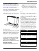
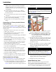
Figure 6: Unit Mounting
Water Piping Connections
General Guidelines
1 Piping can be steel, copper or PVC, but must comply
with local codes.
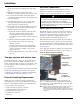
2 Proper ventilation is required for soldering. When
soldering, use a quenching
cloth to protect fan coil
components from overheating damage—melting
insulation, also damage to valves, wiring, electronics,
sensors, etc. See Figure 7. When Daikin provides valve
packages with unions, o-rings are included. When
soldering near unions, remove the o-rings before heating.
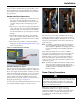
Figure 7: Protect Components From Overheating
3
If sealant compound is not provided for flexible hose
fittings, apply Teflon tape to the connections to help
prevent leaks.
4 Ensure proper insulation of supply and return piping.
Proper insulation prevents loss of fan coil capacity,
overheating of end compartments, and/or moisture
dripping.
5 The piping to and from the unit must be protected from
outside air and freeze conditions. It must be suitably
insulated for condensation and for heat loss or gain.
Penetrations entering the unit end compartments must be
fitted/sealed for unit integrity.
6 Exterior condensate may be an issue if field piping does
not have a control valve. Review the supply and return
header locations in the Dimensions drawing beginning
on page 21. If using a field-assembled piping package,
allow sufficient room to install the secondary drain pan.
Piping for chilled water should not extend over the edges
of the secondary condensate drain pan.
7 Supply and return shutoff valves are recommended at
each unit. The return valve is used for balancing and
should have a “memory stop” so that it can always be
closed off, but can only be re-opened to the proper
position for the flow required.
8 Primary coils are factory-equipped with vents for venting
the system, but secondary coils (preheat or reheat) are
not. If the unit is not equipped with a factory-built piping
packages, then a vent must be added. See step 1, page 8.
9 Be sure to install control valves on the correct fan coil.
Indiscriminate mixing of valves in the field can result in
valves improperly sized for the desired flow rate, which
can result in poor operation and coil freezeups.
10 Install control valves so there is at least 2" (51mm)
minimum clearance to remove the actuator from the
valve body.
Make sure unit is
level front-to-back
and side-to-side.
Use a quenching cloth
when soldering or
brazing to avoid
overheating the piping
components and
creating valve damage
or eratic operation.