
Unit installation


Daikin IM 980-1 9
Installation
main supply line and the fan coil unit. These can be furnished
as part of a factory-installed valve & piping package or they
can be installed in the field. The balancing valve installed on
the return line is used to adjust the water flow to provide the
best performance.
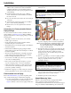
Condensate Drain Connection
1 Connect a copper or plastic pipe to the 7/8 inch copper
pipe on the secondary drain pan. This should be a
mechanical connection that allows easy removal of the
secondary drain pan when servicing the piping end
pocket.
2 Slide the pipe over the drain pan nipple and tighten the
collar on the pipe with a hose clamp (installer supplied).
A drain line pitch of one inch per ten feet of drain line
run must be maintained to provide adequate condensate
drainage.
3 The drain line should be supported to prevent undue
stress on the secondary drain pan. Make sure the drain
line is free of kinks and obstructions and the secondary
drain pan is level.
4 The installer is responsible for adequately insulating
field piping. See External Insulating Requirements‚ page
10 for more information.
Figure 9: Condensate Drain Connection
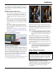
Automatic Changeover Sensor
Two-pipe changeover units require an automatic changeover
switch or pipe sensor that determines heating or cooling mode
based on the supply water temperature. A switch is provided
with a unit-mounted analog thermostat on a two-pipe system.
A sensor is provided with any digital control on a two-pipe
system. On units with a factory-installed valve & piping
package, the factory straps the changeover switch or sensor to
the piping supply water pipe. See Figure 10.
For a two-pipe system with intermediate electric heat, a second
set is required including a changeover switch or sensor.
Figure 10: Changeover switch & sensor attachment
If the unit does not have a factory-installed valve & piping
package, the changeover switch or sensor can be ordered for
field installation. The installer should attach the sensor or auto-
changeover switch parallel to and in direct contact with the
supply water pipe.
Note: The installer is responsible to ensure the changeover
sensor is installed in a location that can sense active
water temperature. Otherwise, the unit may fail to sense
the correct operating mode and disable temperature
control.
When using field-supplied three-way valves, install the
changeover sensor upstream of the valve on the supply water
pipe. When using field-supplied two-way control valves,
install the changeover sensor in a location that will detect
active water temperature. The unit must always be able to
sense the correct system water temperature, regardless of the
control valve position.
Note: The maximum length of the automatic changeover wire
cannot exceed ten feet from the control panel to the
sensor. If the wire extends beyond the unit chassis, use
shielded conductors to eliminate radio frequency
interference (RFI).
Steam Piping Connections
Make piping connections to the steam coil per job
requirements. (
Daikin does not supply steam piping
connections.) Install a 1/2", 15-degree swing check vacuum
breaker in the unused condensate return trapping as close
as possible to the coil.The following procedures are
recommended:
7/8-inch OD
copper pipe
CAUTION!
Coil Damage!
In all steam coil installations, the condensate return connections
must be at the low point of the coil to ensure condensate flows
freely from the coil at all times. Failure to do so may cause
physical coil damage from water hammer, unequal thermal
stresses,freeze-up and/or corrosion.
Changeover switch
Changeover sensor