
Product Specs


2.9.1 Digital Inputs
Any of the 9 GPIOs may be configured as digital inputs. There are five different input configurations as
shown in Table 3-2.
Table 3-2: Input Pin Configurations
Input Pin Configuration
Description
DigitalInput
Configure as high impedance (floating)
DigitalInputPullDown
Configure with internal pull
-
down to GND
DigitalInputPullDownWeak
Configure with external pull
-
down (1 M
Ω) to GND
Di
gitalInputPullUp
Configure with internal pull
-
up to VDD
DigitalInputPullUpWeak
Configure with external pull
-
up (1 M
Ω) to VDD
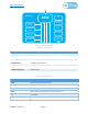
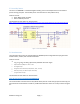
A GPIO digital input example is shown in Figure 3-10.
01 Define PinMode Pin0 As DigitalInputPullUp
02 Class InputPinTest()
3 Shared Event Pin0FallingEdge()
4 // pin0 has gone low, turn on LED for 100ms
5 LedGreen = True // Turn on LED
6 Thread.Sleep(100000) // Sleep for 100 ms
7 LedGreen = False // Turn off LED
8 End Event
9 End Class
Figure 3-10: Input Pin mc-Script
2.9.2 Digital Outputs
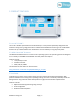
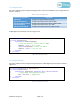
Any of the 9 GPIOs may be configured as digital outputs. A GPIO digital output example is shown in
Figure 3-11.
01 Define PinMode Pin1 As DigitalOutput
02 Class OutputPinTest()
3 Shared Event TogglePin1() RaiseEvent Every 500 milliSeconds
4 // toggle Pin1 every 500 milliseconds
5 Pin1 = Not Pin1 // Toggle Pin1
6 End Event
7 End Class
Figure 3-11: Output Pin mc-Script
©2020 mc-Things Inc. Page | 10