INSTALLATION GUIDE SEALED PELLET STOVE CURVE comfort Air - part 1 - Instructions in English EN
TABLE OF CONTENTS TABLE OF CONTENTS................................................................................................... II INTRODUCTION...........................................................................................................1 1-WARNINGS AND WARRANTY CONDITIONS..................................................................2 2-INSTALLATION..........................................................................................................
INTRODUCTION Dear Customer, our products are designed and manufactured in compliance with European reference Standards for construction products (EN13240 wood-burning stoves, EN14785 pellet-burning appliances, EN13229 fireplaces/wood-burning inserts, EN 12815 wood-burning cookers), with high quality materials and extensive experience in the transformation processes.
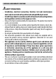
1-WARNINGS AND WARRANTY CONDITIONS SAFETY PRECAUTIONS • Installation, electrical connection, function test and maintenance must only be carried out by authorised and qualified personnel. • Install the product in accordance with all local and national legislation and regulations in force in the region or state. • Only use the fuel recommended by the manufacturer. The product must not be used as an incinerator.
1-WARNINGS AND WARRANTY CONDITIONS • Do not put linen on the product to dry. Any drying racks or similar objects must be kept at a safe distance from the product. Fire hazard. • All liability for improper use of the product is entirely borne by the user and relieves the Manufacturer from any civil and criminal liability.
1-WARNINGS AND WARRANTY CONDITIONS • The product and the cladding must be stored in a dry place and must not be exposed to weathering. • It is recommended not to remove the feet that support the product in order to guarantee adequate insulation, especially if the flooring is made of flammable materials. • In the event of a malfunction with the ignition system, do not force it to light by using flammable materials. • Special maintenance must only be performed by authorised and qualified personnel.
1-WARNINGS AND WARRANTY CONDITIONS INFORMATION: Please contact the retailer or qualified personnel authorised by the company to resolve a problem. • You must only use the fuel specified by the manufacturer. • When the product is switched on for the first time it is normal for it to emit smoke due to the paint heating for the first time. Therefore make sure the room in which it is installed is well ventilated. • Check and clean the smoke extraction pipes regularly (connection to the chimney).
1-WARNINGS AND WARRANTY CONDITIONS EXCLUSIONS The guarantee does not cover malfunctions and/or damage to the appliance that arise due to the following causes: • Damage caused during transportation or relocation • all parts that develop faults due to negligence or improper use, incorrect maintenance, installation that does not comply with the manufacturer’s instructions (always refer to the installation and use manual provided with the appliance) • incorrect dimensioning with regards to the use or faults in
1-WARNINGS AND WARRANTY CONDITIONS SPARE PARTS In the event of a malfunction, consult the retailer who will forward the call to the Technical Assistance Service. Use only original spare parts. The retailer or service centre can provide all necessary information regarding spare parts. We do not recommend waiting for the parts to be worn before having them replaced. It is important to perform regular maintenance.
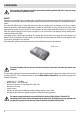
2-INSTALLATION The instructions in this chapter refer explicitly to the Italian installation regulation UNI 10683. In any case, always observe the domestic regulations in force. PELLETS Wood pellets are manufactured by hot-extruding compressed sawdust which is produced during the working of natural dried wood. The compactness of the material is guaranteed by the lignin contained in the wood itself and allows pellets to be produced without glue or binders.
2-INSTALLATION FOREWORD The installation position must be chosen according to the room, to the smoke extraction system, to the chimney flue. Check with local authorities whether there are any restrictive regulations in force regarding the combustion air inlet, the smoke outlet system, the flue or the chimney cap.
2-INSTALLATION FOREWORD This chapter on the Smoke Flue has been produced in reference to the prescriptions of European regulations (EN13384 - EN1443 - EN1856 - EN1457). The chapter provides indications for installing an efficient and correct smoke flue but is under no circumstances to substitute the regulations in force, which the qualified technician must be in possession of.
2-INSTALLATION TECHNICAL CHARACTERISTICS Have the efficiency of the flue checked by an authorised technician. The flue must be sealed against flue gasses, in a vertical direction without narrowing, be made with materials impermeable to smoke, condensation, thermally insulated and suitable to resist normal mechanical stress over time (we recommend fireplaces made of A/316 or refractory material with insulated round section double chamber).
2-INSTALLATION ROOF AT 60° ROOF AT 45° B B C C D D E A F 60° A = MIN. 2.60 metres B = DISTANCE > 1.20 metres C = DISTANCE < 1.20 metres D = 0.50 metres ABOVE HIGHEST POINT E = 2.10 metres F = REFLUX ZONE FIGURE 5 A 45° A = MIN. 2.00 metres B = DISTANCE > 1.30 metres C = DISTANCE < 1.30 metres D = 0.50 metres ABOVE HIGHEST POINT E = 1.50 metres F = REFLUX ZONE E F FIGURE 6 DIMENSIONING The drop in pressure (draft) of a flue depends on its height.
2-INSTALLATION MAINTENANCE The flue must be kept clean, since the deposit of soot or unburned oils reduces the cross-section reducing the draft and thus compromising the efficient functioning of the heater and, if large build-ups accumulate, can catch fire. The flue and chimney must be cleaned and checked by a qualified chimney sweep at least once a year. Once the maintenance has been performed, request a written declaration that the device is safe. Failure to clean the system jeopardises the safety.
2-INSTALLATION EXTERNAL AIR INLET It is mandatory to provide an adequate external air intake that supplies the combustion air required for the product to work properly. The flow of air between the outside and the installation room may be direct, through an inlet in an external wall of the room; or indirect, via air intake from adjoining rooms and connecting permanently with the installation room (see Figure 9 b). Adjoining areas may not include sleeping areas, garages or general areas with a fire hazard.
2-INSTALLATION DISTANCE (metres) The air inlet must be at a distance of: 1.5 m UNDER Windows, doors, smoke outlets, cavities, .... 1.5 m HORIZONTALLY Windows, doors, smoke outlets, cavities, .... 0.3 m ABOVE Windows, doors, smoke outlets, cavities, .... 1.5 m AWAY from smoke outlet CONNECTION TO FLUE The connection between the flue and the appliance must be via a smoke duct that conforms with EN 1856-2.
2-INSTALLATION EXAMPLES OF CORRECT INSTALLATION 1 U F E V I 2 1. Installation of Ø150mm flue with hole for the passage of the tube increased by: minimum 100 mm around the tube if next to non flammable parts such as cement, brick, etc.; or minimum 300 mm around the tube (or as prescribed by data tags) if next to flammable parts such as wood etc. In both cases, install suitable insulation between the flue and the ceiling.
3-DRAWINGS AND TECHNICAL FEATURES DRAWINGS AND CHARACTERISTICS CURVE COMFORT AIR STOVE DIMENSIONS 1200 560 Ø80 209 290 187 196 560 Ø5 0 104 100 Ø58 Ø80 Ø80 560 Technical Dept.
3-DRAWINGS AND TECHNICAL FEATURES TECHNICAL CHARACTERISTICS Nominal output power Minimum power output Efficiency at Max Efficiency at Min Temperature of exhaust smoke at Max Temperature of exhaust smoke at Min Particulate /OGC / Nox (13%O2) CO at 13% O2 at Min and at Max CO2 at Min and at Max Recommended draught at Max*** power Minimum draft allowed at minimum power Smoke mass Hopper capacity Type of pellet fuel Pellet hourly consumption Autonomy Heatable volume m3 Combustion air inlet Smoke outlet Air intl
4-UNPACKING PREPARATION AND UNPACKING The packaging consists of a recyclable cardboard box in line with RESY standards and a wooden pallet. All packaging materials can be reused for similar use or eventually disposed of as urban solid waste, in compliance with the regulations in force. After having removed the packaging make sure the product is intact. Handle the product with suitable means paying attention to the applicable safety regulations in force.
4-UNPACKING u s REMOVING FASTENING BRACKETS To remove the stove from the pallet, you must remove the two screws ‘’u’’ and plate ‘’s’’ from the stove’s foot. There are four brackets “s”.
4-UNPACKING Position the stove and connect it to the flue pipe. Use the four adjustable feet (J)to get the stove correctly levelled so that the smoke outlet is lined up with the connecting pipe. If the stove needs to be connected to an outlet pipe which goes through the rear wall (to connect to the flue), take utmost care to make sure that the joint is not forced. If the stove smoke outlet is forced or used improperly to lift it or position it, the operation of the stove can be damaged irreparably. J J 1.
5-CLADDING ASSEMBLY On delivery, the Curve stove has no ceramic cladding, as shown in the image below. The fixing brackets are in part already mounted on the structure and in part on the ceramics (see explanations below). Take the box with the ceramics (figure below) and prepare them for installation. The ceramic surfaces are to be assembled to the structure in accordance with the indications on the following pages. Live electrical parts: only power the product after completing assembly.
5-CLADDING ASSEMBLY DISASSEMBLING THE TOP The top is centrally secured to the structure via two “u” screws. Lift the door on the tank side (rear semicircle) and remove the two “u” screws. At the front instead, the bracket on the top must be placed on the structure of the stove via two rubber pads (“a”). Ensure the top is placed safely until the ceramic cladding is installed. a u Technical Dept.
5-CLADDING ASSEMBLY INSTALLING THE FRONT LOWER PANEL To assemble the ceramic panel proceed as follows: • • open decorative door “N” and also firebox door “O” (see opening instructions) • • remove frame “T1” from the structure by also taking out screw “w”, lifting frame “T1” so that the two joints “x” come out of holes “y” in place on the stove’s structure • • then take ceramic panel type “A” and secure it to frame “T1” with the four screws (“k”) supplied with the ceramic panels.
5-CLADDING ASSEMBLY • now take frame assembly “T1” and ceramic panel “A” and place the latter on the structure by inserting the two joints “x” in the holes on structure “y”. Secure everything to the structure with screw “w”. k T1 A k w y A y x x Technical Dept.
5-CLADDING ASSEMBLY INSTALLING THE FRONT UPPER PANEL The assembly procedure is similar to the previous one: • from the structure, remove frame “T2” by taking out the two screws “w” at the top and screw “z” from below.
5-CLADDING ASSEMBLY • take ceramic panel type “B” and secure it to frame “T2” with the four screws (“k”) supplied with the ceramic panels. B T2 k k • now take the frame assembly “T2” and ceramic panel “B” and place back the latter on the structure via the two screws “w” at the top and the “z” screw at the bottom (to be secured under the ceramic panel) w T2 w B z Technical Dept.
5-CLADDING ASSEMBLY HOW TO USE THE TEMPLATE TO SECURE THE TOP FRONT CERAMIC PANEL After removing frame “T2” from the structure of the stove, in line with the instructions reported in the above paragraph, take template “M” to position the ceramic panel and secure it at the top of frame “T2” with the screws supplied. As described above, secure ceramic panel “B” to frame “T2” by ensuring that the top of the ceramic panel rests against template “M”.
5-CLADDING ASSEMBLY SIDE PANEL ASSEMBLY Attention! The frame features slotted holes, thereby allowing for a slight adjustment of the ceramic panels. A template will be provided to the customer to position the ceramic panels from above. Proceed as follows: • from the structure, remove frame “T3” by taking out the two screws “w” • Lift frame “T3” so that holes “y” on the frame can come out from hooks “x” on the structure w w T3 x y Technical Dept.
5-CLADDING ASSEMBLY • • now take a type “C” ceramic panel, position it on the frame with the template supplied and secure it to frame “T3”.
5-CLADDING ASSEMBLY • • with the ceramic panels mounted, go ahead with the final fixing to the structure at the bottom, insert the holes of the frame of the ceramic panels to the hooks on the structure and go ahead with the fixing with the two screws “w” at the top w Technical Dept.
5-CLADDING ASSEMBLY Proceed in the same way also for the panel on the left-hand side of the stove: • remove frame “T4” from the stove • secure ceramic panels “F”, “G” and “H” by taking into account the adjustments for an alignment with the other ceramic surfaces already installed F T4 G H • 32
5-CLADDING ASSEMBLY HOW TO USE THE TEMPLATE TO SECURE THE SIDE CERAMIC PANEL (same procedure for the right and left panel).. Attention! With template “M” start to position the first ceramic panel at the top. After removing frame “T3” from the structure of the stove, in line with the instructions reported in the above paragraph, take template “M” to position the ceramic panel and secure it at the top of frame “T3” with the screws supplied.
5-CLADDING ASSEMBLY REAR PANEL ASSEMBLY • • Remove frame “T5” from the structure by taking out the two screws “w” at the top and loosen the two screws “x” at the bottom lift frame “T5” from the structure of the stove and remove it NOTE: there is no need to remove panel “O” to remove panel “T5”. On panel “O” there are two holes that can be used for loosening and two screws “x” to take out panel “T5”.
5-CLADDING ASSEMBLY • • • • take ceramic panel type “I” and secure it to frame “T5” via the four screws “k” (consider it as the base to start fixing the template) then secure ceramic panel type “L” by again using the positioning template secure ceramic panel “L” to frame “T5” via the four screws “k” try and secure the frame with the ceramic panels on the structure to check the alignment with the other ceramic panels; perform the necessary adjustments as required I T5 L k k Technical Dept.
5-CLADDING ASSEMBLY • when the checks have been carried out, secure frame “T5” with the ceramic panels on the structure, by using the two screws “x” to secure the bottom of the panel and the two screws “w” to fix the top w T5 I L x 36
5-CLADDING ASSEMBLY HOW TO USE THE TEMPLATE TO SECURE THE REAR CERAMIC PANEL Attention! With template “M” start to position the first ceramic panel at the top. After removing frame “T5” from the structure of the stove, in line with the instructions reported in the above paragraph, take template “M” to position the ceramic panel and secure it at the top of frame “T5” with the screws supplied and pre-secured to the template.
6-OPENING THE DOORS The Curve stove is fitted with two doors. To open decorative door “E”, insert cold handle “Z” into the designated joint on the door itself. To open firebox door “F”, insert the cold handle into the hole of handle “P” and pull. Attention! Only open the doors when the stove is switched off and cold.
7-REMOVING THE BACK FOR MAINTENANCE REAR PANEL If it is necessary to intervene on any stove component, proceed as follows to remove the rear panel “O”. • remove the two screws “s”, so that element “P” can be removed • remove the four screws “v” • now panel “O” can be completely removed from the structure of the stove (even when the stove has been installed, therefore with the smoke pipe connected) v O P s v Technical Dept.
8-CONNECTIONS TO ADDITIONAL DEVICES MODEM INSTALLATION “M”/WEB-WIFI INTERFACE “N” Install the Modem “M” or the Web-Wi-Fi-Interface “N” using the holes on the back of the product and follow the instructions on the product chosen. During installation we recommend breaking the knock-out panels in the fixing flaps so that the modem or the web interface rest perfectly against the structure.
8-CONNECTIONS TO ADDITIONAL DEVICES Comfort Air ducting Comfort Air stoves can channel the air into other rooms through the connection with the accessory pipes to the rear extension provided as standard. If you do not wish to channel the air, the hot air may be let out through the rear vent without connecting any pipe. Technical Dept.
9-LOADING THE PELLETS LOADING THE PELLETS The fuel is loaded from the top of the stove by lifting rear top hatch “S” and pellet loading door “T”. To open door “T”, insert the cold handle into the designated hole “f”. Pour the pellets in slowly so that they are deposited at the bottom of the hopper. If loading pellets when the stove is running, open the door of the tank using the stove mitten that comes with the stove itself. When loading, do not let the pellet bag come into contact with hot surfaces.
MCZ GROUP S.p.A. Via La Croce n°8 33074 Vigonovo di Fontanafredda (PN) – ITALY Telephone: +39 0434/599599 r.a. Fax: +39 0434/599598 Internet: www.mcz.it e-mail: mcz@mcz.it 8901606200 REV.