INSTALLATION GUIDE SEALED PELLET STOVE CURVE comfort Air - part 2 - Instructions in English EN
TABLE OF CONTENTS TABLE OF CONTENTS................................................................................................... II 10-FIRST START-UP......................................................................................................3 11-REMOTE CONTROL MAX...........................................................................................4 12-EMERGENCY PANEL...............................................................................................11 13-OPERATION...........
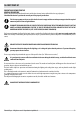
10-FIRST START-UP PRECAUTIONS BEFORE START-UP GENERAL PRECAUTIONS Remove all parts that may burn from the brazier and the glass (manual, various adhesive labels or any polystyrene). Check that the brazier is positioned correctly and rests properly on the base. The first start-up may not be successful as the feed screw is empty and does not always manage to load the required amount of pellets in time to light the flame.
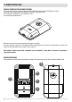
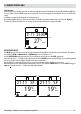
11-REMOTE CONTROL MAX GENERAL FEATURES OF THE LCD REMOTE CONTROL The remote control works at a transmission frequency of 434.5 MHz. Power the product with 3 AAA batteries as follows: Remove the battery compartment cover by sliding it downwards (according to the arrow). Insert the batteries according to the correct polarity (+) and (-). Close the battery compartment cover. When the remote control is powered it automatically prompts to set the time.
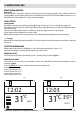
11-REMOTE CONTROL MAX REMOTE CONTROL OPERATION General rules By pressing key A for 1” the product is switched on and off. Key C is used to make all changes. Key E is used to confirm the changes. By pressing key B one selects the product operating mode. Via key D one browses the FAN and SLEEP setting. Whichever the mode is, press key A briefly (or leave the keypad idle for 7”) to go back to the initial display.
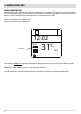
11-REMOTE CONTROL MAX MANUAL POWER FUNCTION this function allows you to set the power of the flame from a minimum of 1 to a maximum of 5. The power levels correspond to a different value of fuel consumption, setting 5 heats the room in less time and setting 1 can keep the room temperature stable for a longer period of time. The set flame is automatically set to a minimum when the set temperature value is reached.
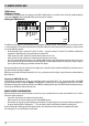
11-REMOTE CONTROL MAX TIMER Mode (TIMER) Select this operating mode to switch the product on and off automatically, according to 6 customised time slots (P1 – P6). The following can be set for each time slot: • Switch-on time • Switch-off time • Desired room temperature in the time slot • Days of the week in which the time slot is active When the stove is switched on (manually via key A or automatically via a time slot) the product works in the automatic mode described above.
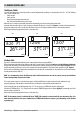
11-REMOTE CONTROL MAX Room ventilation Room ventilation can be adjusted as desired in all 4 operating modes described above (Manual, Automatic, Timer, Eco). Simply perform this operation: from the basic display, press key D to access the VENTILATION adjustment mode (Fig. 6). Then press key C (arrows) to set the desired ventilation by selecting one of the 5 levels available, independent from the flame level.
11-REMOTE CONTROL MAX Sleep function The sleep mode allows to quickly set the time at which the product must switch off. This function is only available in MAN and AUTO mode. It is set as follows: from the POWER setting (by pressing key D - see previous paragraph), press key D again to access the SLEEP mode setting. Via key C one can adjust the shutdown time in 10 minute intervals.
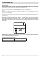
11-REMOTE CONTROL MAX TIMER settings TIMER time slot display In TIMER mode, to display the time slots simply press key D for 2”. With key C one can scroll the 6 time slots freely, quickly checking the saved settings (figure 8). By pressing key D or A one goes back to the basic display. Modifying the TIMER time slots MO TU WE TH FR SA SU 6:30 8:00 P120°C ON OFF TIMER OFF ON TIMER ECO To modify a time slot, display it as described in the previous paragraph and then press key E.
-REMOTE CONTROL MAX The emergency panel is found at the back of the stove. The panel is used to detect any malfunctions and also for product control if the remote control is not working. H A B C D E F G KEY A - DISPLAY; indicates a series of information on the stove, as well as the identification code of any malfunction.
11-REMOTE CONTROL MAX INSTALLATION OF THE CONTROL PANEL ANTENNA • • Take Antenna “A” from the bag containing the instructions Tighten Antenna “A” clockwise on screw “V” near the control panel until the mobile part of the antenna is at the top. Attention! Fully tighten the antenna without forcing it so as to avoid damaging the reception.
11-REMOTE CONTROL MAX ELECTRICAL CONNECTION First connect the power cable to the back of the stove and then to a wall socket. The main switch must only be activated to switch the stove on; otherwise, it is advisable to keep it switched off. It is recommended to disconnect the power cable when the stove is not used. ELECTRICAL STOVE CONNECTION The cable must never come into contact with the smoke exhaust pipe or any other part of the stove.
11-REMOTE CONTROL MAX Switch-on/off from the emergency panel If the remote control is faulty or the batteries are flat, the product can be operated in safe mode via the rear emergency panel. In this configuration, the stove can only operate in manual mode and with the possibility to choose between 3 power levels. • SWITCHING THE STOVE ON WITHOUT THE REMOTE CONTROL To switch the stove on move selector “D” to the ON position.
11-REMOTE CONTROL MAX Feed screw loading function This function can only be activated when the stove is off and allows the pellets to be loaded into the loading system (feed screw). It can be used each time the pellets finish in the hopper (see alarm A02). It is useful to prevent failed start-ups (alarm A01) due to the hopper being empty.
11-REMOTE CONTROL MAX Modifying the pellet recipe This function is for adapting the stove to the type of pellet in use. As there are many types of pellet available on the market, operation of the stove can vary considerably according to the quality of the fuel.
14-SAFETY DEVICES SAFETY DEVICES The product is fitted with the following safety devices. SMOKE TEMPERATURE PROBE It detects the temperature of the smoke, thereby enabling start-up or stopping the product when the temperature drops below the preset value. PELLET HOPPER TEMPERATURE PROBE If the temperature exceeds the preset safety value, it immediately stops the product, which must cool down before the stove is restarted.
15-ALARMS ALARM ALERTS In the event an operating anomaly occurs the stove starts switching off due to the alarm and informs the user of the type of fault that has taken place via a 3 digit code which stays displayed on the rear emergency panel. The alarm is indicated permanently by the relative 3 digit code, by a flashing red LED that lights up on the emergency panel and an intermittent sound signal for the first 10 minutes of the alarm.
15-ALARMS A13 Electronic control unit overheating The structure is too hot because the product has been used for too long at the maximum power or there is poor ventilation. When the stove is sufficiently cold, press button B on the control panel or OFF on the remote control to cancel alarm A13. Once the alarm is cancelled, the product can be switched on normally. A14 Faulty air flow rate sensor This alarm does not block the stove, just a warning is displayed.
15-ALARMS Mechanical stove block The following conditions may cause the mechanical stove block: • • • Structure overheating (“A03”) Smoke overheating (“A04”) During stove operation air has entered the combustion chamber or there is an obstruction in the flue (“A05”) The block is signalled on the display and with a sound signal. In this situation the shutdown stage is activated automatically.When this procedure is started, any test operation to restore the system is useless.
15-ALARMS In the event that alarm A18 is triggered often, please note that: A18 INTERVENTO SICUREZZE Porta stufa aperta Chiudere la porta Sportello di caricamento combustibile Chiudere lo sportello. aperto Abbassare il livello di combustibile nel serbatoio. Pressostato aria Difficoltà di tiraggio o intasamento del braciere. Verificare se il braciere è intasato dalle incrostazioni ed eventualmente pulirlo. Controllare ed eventualmente pulire il condotto fumario e l’ingresso dell’aria.
15-ALARMS If all the above checks are negative, it is likely that the depression inside the stove drops due to poor performance of the flue, especially when the machine is operating at minimum speed for a long time. In this case it is possible to make small adjustments that allow you to increase the operating speed of the smoke fan to increase the depression inside the product, or make it less sensitive to the intervention of the pressure switch by changing its position mechanically.
15-ALARMS Changing the position of the pressure switch ATTENTION! All the operations must be performed with the product completely cold and the plug disconnected. Disconnect the product from the 230V power supply before performing any operation. One can then act on the air pressure switch by changing the installation position. The pressure switch is fitted behind the electronic board of the stove.
16-RECOMMENDATIONS FOR SAFE USE ONLY CORRECT INSTALLATION AND APPROPRIATE MAINTENANCE AND CLEANING OF THE APPLIANCE CAN GUARANTEE CORRECT OPERATION AND SAFE USE OF THE PRODUCT. We would like to inform you that we are aware of cases of malfunctioning of domestic pellet-fuelled heating products, mainly due to incorrect installation and use, as well as inadequate maintenance. We would like to assure you that all of our products are extremely safe and certified according to European standards of reference.
17-CLEANING EXAMPLE OF A CLEAN BRAZIER EXAMPLE OF A DIRTY BRAZIER Only by properly servicing and cleaning the product is it possible to ensure its safety and correct operation. CAUTION! All the cleaning operations of all parts must be performed with the product completely cold and the plug disconnected. Disconnect the product from the 230V power supply before performing any maintenance operation. The product requires little maintenance if used with certified good quality pellets.
17-CLEANING REMEMBER THAT ONLY A CORRECTLY POSITIONED AND CLEAN BRAZIER CAN GUARANTEE SAFE IGNITION AND OPTIMAL OPERATION OF YOUR PELLET PRODUCT. IN CASE OF FAILED IGNITION AND AFTER ANY OTHER LOCK STATE OF THE PRODUCT, IT IS ESSENTIAL TO EMPTY THE BRAZIER BEFORE EVERY RESTART. For the brazier to be cleaned properly, remove it from its housing completely and thoroughly clean all the holes and the grate on the bottom.
17-CLEANING CLEANING THE AIR FILTER A wire mesh air filter is found at the back of the stove, whose purpose is to prevent dirt entering the motor body and the internal sensor. It is recommended to check that the filter is clean every 15/20 days. If needed remove fluff or the material that has deposited on it. Inspection and cleaning are required more frequently if there are pets in the house. Simply remove the filter to clean. To clean it use a brush or a damp cloth or compressed air.
17-CLEANING PERIODIC CLEANING PERFORMED BY A QUALIFIED TECHNICIAN CLEANING THE HEAT EXCHANGER AND THE LOWER COMPARTMENT Half-way through the winter season, but especially at the end, the compartment through which the exhaust smoke passes will need to be cleaned. This cleaning process is mandatory in order to facilitate the general removal of all combustion residue, before it becomes very difficult to remove it due to the humidity compacting it over time.
17-CLEANING CLEANING THE EXCHANGER CLEANING THE UPPER COMPARTMENT Clean the upper exchanger when the stove is cold and without the cladding in question. After removing the cap for lower cleaning “n” (see previous paragraph), use a stiff rod or a bottle brush to scrape the firebox walls (see arrow) so that the ash falls into the lower compartment.
17-CLEANING Use a stiff rod or a bottle brush to scrape the firebox walls (see arrow - at the right and left of the firebox respectively) so that the ash falls into the lower compartment. H Use a vacuum cleaner nozzle to vacuum up any remaining ash and dust on the exchanger (see arrow).
17-CLEANING Also vacuum under the top to remove any accumulated dust. Then thoroughly clean the lower exchanger, replace any gaskets if needed, and reassemble. Technical Dept.
17-CLEANING CLEANING THE SMOKE DUCT AND GENERAL CHECKS Clean the smoke extractor duct, especially around the “T” joints, bends and any horizontal sections. For information on cleaning the flue, contact a chimney sweep. Check the seal of the ceramic fibre gaskets on the door of the stove. If necessary, order new replacement seals from the retailer or contact an authorized service centre to carry out this task.
17-CLEANING END-OF-SEASON SHUTDOWN At the end of each season, before switching the product off, it is recommended to remove all the pellets from the hopper with a vacuum cleaner with a long pipe. We recommend removing the unused pellet from the tank because it can retain humidity.
18-FAULTS/CAUSES/SOLUTIONS ATTENTION! All repairs must only be carried out by a specialised technician, with the product switched off and the plug disconnected. ANOMALY POSSIBLE CAUSES The pellets are not fed into the The pellet hopper is empty. combustion chamber. Sawdust has blocked the feed screw. SOLUTIONS Fill the hopper with pellets. Empty the hopper and remove the sawdust from the feed screw by hand. Faulty gear motor. Replace the gear motor. Faulty circuit board. Replace the circuit board.
18-FAULTS/CAUSES/SOLUTIONS ANOMALY POSSIBLE CAUSES The product works for a few minutes Start-up phase is not completed. and then switches off. Temporary power cut. Clogged smoke duct. SOLUTIONS Repeat start-up. Switch it back on. Clean the smoke duct. Faulty or malfunctioning temperature Check and replace the probes. probes. Pellets accumulate in the brazier, the Insufficient combustion air. glass of the door gets dirty and the flame is weak.
18-FAULTS/CAUSES/SOLUTIONS ANOMALY POSSIBLE CAUSES SOLUTIONS The air fan does not switch on. The product has not reached the Wait. temperature. The remote control does not work. The remote control battery is flat. Replace the battery. Remote control faulty. Replace the remote control. The product always runs at maximum The room thermostat is in the maximum Reset the temperature of the remote power when in automatic mode. position. control. The product does not switch on.
19-CIRCUIT BOARD LIVE ELECTRICAL CABLES DISCONNECT THE POWER SUPPLY CABLE 230V BEFORE CARRYING OUT ANY OPERATIONS ON THE ELECTRICAL BOARDS LOW VOLTAGE BASSA TENSIONE HIGH ALTAVOLTAGE TENSIONE 13 12 10 2 1 3 GND SIGNAL 5V GND SIGNAL 5V GND SIGNAL 12V - 11 + ROSSO BLU 4 9 15 12V GND + - 8 14 5 6 7 COMFORT AIR STOVE WITH 2 FANS WIRING KEY 1. 2. 3. 4. 5. 6. 7. 8.
MCZ GROUP S.p.A. Via La Croce n°8 33074 Vigonovo di Fontanafredda (PN) – ITALY Telephone: +39 0434/599599 r.a. Fax: +39 0434/599598 Internet: www.mcz.it e-mail: mcz@mcz.it 8901615900 REV.