INSTALLATION GUIDE PELLET FIREPLACE VIVO 90 PELLET COMFORT AIR COMFORT AIR SLIM MODEL COMFORT AIR BASIC MODEL Instructions in English EN
TABLE OF CONTENTS TABLE OF CONTENTS................................................................................................... II INTRODUCTION...........................................................................................................1 1-WARNINGS AND WARRANTY CONDITIONS..................................................................2 2-INSTALLATION..........................................................................................................
INTRODUCTION Dear Customer, our products are designed and manufactured in compliance with European reference Standards for construction products (EN13240 wood-burning stoves, EN14785 pellet-burning appliances, EN13229 fireplaces/wood-burning inserts, EN 12815 wood-burning cookers), with high quality materials and extensive experience in the transformation processes.
1-WARNINGS AND WARRANTY CONDITIONS SAFETY PRECAUTIONS • Installation, electrical connection, function test and maintenance must only be carried out by authorised and qualified personnel. • Install the product in accordance with all local and national legislation and regulations in force in the region or state. • Only use the fuel recommended by the manufacturer. The product must not be used as an incinerator.
1-WARNINGS AND WARRANTY CONDITIONS • Do not put linen on the product to dry. Any drying racks or similar objects must be kept at a safe distance from the product. Fire hazard. • All liability for improper use of the product is entirely borne by the user and relieves the Manufacturer from any civil and criminal liability.
1-WARNINGS AND WARRANTY CONDITIONS • The product and the cladding must be stored in a dry place and must not be exposed to weathering. • It is recommended not to remove the feet that support the product in order to guarantee adequate insulation, especially if the flooring is made of flammable materials. • In the event of a malfunction with the ignition system, do not force it to light by using flammable materials. • Special maintenance must only be performed by authorised and qualified personnel.
1-WARNINGS AND WARRANTY CONDITIONS INFORMATION: Please contact the retailer or qualified personnel authorised by the company to resolve a problem. • You must only use the fuel specified by the manufacturer. • When the product is switched on for the first time it is normal for it to emit smoke due to the paint overheating for the first time. Therefore make sure the room in which it is installed is well ventilated. • Check and clean the smoke extraction pipes regularly (connection to the chimney).
1-WARNINGS AND WARRANTY CONDITIONS EXCLUSIONS The guarantee does not cover malfunctions and/or damage to the appliance that arise due to the following causes: • Damage caused during transportation or relocation • all parts that develop faults due to negligence or improper use, incorrect maintenance, installation that does not comply with the manufacturer’s instructions (always refer to the installation and use manual provided with the appliance) • incorrect dimensioning with regards to the use or faults in
1-WARNINGS AND WARRANTY CONDITIONS SPARE PARTS In the event of a malfunction, consult the retailer who will forward the call to the Technical Assistance Service. Use only original spare parts. The retailer or service centre can provide all necessary information regarding spare parts. We do not recommend waiting for the parts to be worn before having them replaced. It is important to perform regular maintenance.
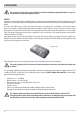
2-INSTALLATION The instructions in this chapter refer explicitly to the Italian installation regulation UNI 10683. In any case, always observe the domestic regulations in force. PELLETS Wood pellets are manufactured by hot-extruding compressed sawdust which is produced during the working of natural dried wood. The compactness of the material is guaranteed by the lignin contained in the wood itself and allows pellets to be produced without glue or binders.
2-INSTALLATION FOREWORD The installation position must be chosen according to the room, to the smoke extraction system, to the chimney flue. Check with local authorities whether there are any restrictive regulations in force regarding the combustion air inlet, the smoke outlet system, the flue or the chimney cap.
2-INSTALLATION FOREWORD This chapter on the Smoke Flue has been produced in reference to the prescriptions of European regulations (EN13384 - EN1443 - EN1856 - EN1457). The chapter provides indications for installing an efficient and correct smoke flue but is under no circumstances to substitute the regulations in force, which the qualified technician must be in possession of.
2-INSTALLATION TECHNICAL CHARACTERISTICS Have the efficiency of the flue checked by an authorised technician. The flue must be sealed against flue gasses, in a vertical direction without narrowing, be made with materials impermeable to smoke, condensation, thermally insulated and suitable to resist normal mechanical stress over time (we recommend fireplaces made of A/316 or refractory material with insulated round section double chamber).
2-INSTALLATION ROOF AT 60° ROOF AT 45° B B C C D D E A F 60° A = MIN. 2.60 metres B = DISTANCE > 1.20 metres C = DISTANCE < 1.20 metres D = 0.50 metres ABOVE HIGHEST POINT E = 2.10 metres F = REFLUX ZONE FIGURE 5 A 45° A = MIN. 2.00 metres B = DISTANCE > 1.30 metres C = DISTANCE < 1.30 metres D = 0.50 metres ABOVE HIGHEST POINT E = 1.50 metres F = REFLUX ZONE E F FIGURE 6 DIMENSIONING The drop in pressure (draft) of a flue depends on its height.
2-INSTALLATION MAINTENANCE The flue must be kept clean, since the deposit of soot or unburned oils reduces the cross-section reducing the draft and thus compromising the efficient functioning of the heater and, if large build-ups accumulate, can catch fire. The flue and chimney must be cleaned and checked by a qualified chimney sweep at least once a year. Once the maintenance has been performed, request a written declaration that the device is safe. Failure to clean the system jeopardises the safety.
2-INSTALLATION EXTERNAL AIR INLET It is mandatory to provide an adequate external air intake that supplies the combustion air required for the product to work properly. The flow of air between the outside and the installation room may be direct, through an inlet in an external wall of the room; or indirect, via air intake from adjoining rooms and connecting permanently with the installation room (see Figure 9 b). Adjoining areas may not include sleeping areas, garages or general areas with a fire hazard.
2-INSTALLATION DISTANCE (metres) The air inlet must be at a distance of: 1.5 m UNDER Windows, doors, smoke outlets, cavities, .... 1.5 m HORIZONTALLY Windows, doors, smoke outlets, cavities, .... 0.3 m ABOVE Windows, doors, smoke outlets, cavities, .... 1.5 m AWAY from smoke outlet CONNECTION TO FLUE The connection between the flue and the appliance must be via a smoke duct that conforms with EN 1856-2.
2-INSTALLATION EXAMPLES OF CORRECT INSTALLATION 1 U F E V I 2 1. Installation of Ø150mm flue with hole for the passage of the tube increased by: minimum 100 mm around the tube if next to non flammable parts such as cement, brick, etc.; or minimum 300 mm around the tube (or as prescribed by data tags) if next to flammable parts such as wood etc. In both cases, install suitable insulation between the flue and the ceiling.
3-DRAWINGS AND TECHNICAL FEATURES DRAWINGS AND CHARACTERISTICS VIVO 90 PELLET COMFORT AIR DIMENSIONS 179* 560 686 Ø200 600 Ø200 75* 38* 48 Ø8 0 188 442 48 900 Ø100 250 Ø100 449 *COMBUSTION AIR FITTING Technical Dept.
3-DRAWINGS AND TECHNICAL FEATURES TECHNICAL CHARACTERISTICS Nominal output power Minimum power output Efficiency at Max Efficiency at Min Temperature of exhaust smoke at Max Temperature of exhaust smoke at Min Particulate /OGC / Nox (13%O2) CO at 13% O2 at Min and at Max CO2 at Min and at Max Recommended draught at Max*** power Minimum draft allowed at minimum power Smoke mass Hopper capacity Type of pellet fuel Pellet hourly consumption Autonomy Heatable volume m3 Combustion air inlet Smoke outlet Air intl
4-UNPACKING PREPARATION AND UNPACKING The product is supplied in a single package. Inside it are the pipe, the loading hatch and the ventilation grilles. A box is placed on top of this packing containing the comfort air Slim or Basic Kit. Open the packing, remove the product from the pallet and place it in the selected position, ensuring it complies with the specifications.
5-INSTALLATION AND ASSEMBLY SMOKE EXHAUST CONNECTION A COMBUSTION AIR During operation a certain amount of air is drawn from the room in which the product is installed and this air must be supplemented through an external air inlet. In this product the input of combustion air is directly from the grille, placed on the pellet loading hatch, in an autonomous manner. It is necessary to connect the pipe diam. 65 mm the product is equipped with and the hatch as shown in the figure.
5-INSTALLATION AND ASSEMBLY HOT AIR OUTLET DUCTING The product has the option of distributing hot air according to the Forced Convection method using a forced ventilation kit (supplied). The product can be supplied with two types of kit: • Comfort Air Slim. • Comfort Air Basic. The main features of the two kits are: • Comfort Air Slim Kit - multi 12 diffuser, diam.60 mm ducting and motor between insert and diffuser. • Comfort Air Basic Kit - multi 20 diffuser, diam.
5-INSTALLATION AND ASSEMBLY ELECTRIC FAN CONNECTION The kit supplied includes 2 silicone cables, 2.5 metre long for wiring the fans. Start by wiring as follows: In position 2 connect the yellow/green wire while in position 1 connect the remaining two wires (the colour sequence does not matter as the fans have no polarisation) (fig.7). The terminal board where the fan wires are to be connected is screwed into the structure upright, at the top (fig.8).
5-INSTALLATION AND ASSEMBLY POSITIONING Before placing the product, assess optimal positioning condition. The product can be installed in an already existing traditional fireplace or as new installation. Furthermore, to raise the product, an iron support may be purchased separately (see special accessory price list - optional) or a platform may be constructed on site as long as stability and safety of the Vivo 90 insert is assured. The optional support raises the product by min. 50 cm to 65 cm maximum.
5-INSTALLATION AND ASSEMBLY FASTENING TO THE BASE OF THE INSERT It is obligatory to anchor the product to a plane during annual maintenance operations by the authorised technician, the combustion chamber may be extracted from its seat with the aid of two retractable guides. Proceed as follows to fasten the insert: • The depth of the insert from the inside of the frame is 590 mm.
5-INSTALLATION AND ASSEMBLY The product may be installed at the desired height, building a suitable platform on site. This support must be constructed in nonflammable material. The company disclaims all liability for any damage to objects and persons should the above-mentioned precautions not be complied with.
5-INSTALLATION AND ASSEMBLY SIDE CHUTE ASSEMBLY In the event of opting for side chute installation, the distance from the machine axis to the wall must be 80 cm maximum (picture on the side). To position the chute, proceed as follows: • Connect the pipe supplied to Vivo 80 Pellet ensuring it is rotated to the side, and fasten it with the clamp. • Connect the pipe (in the top section) to the mouth of the hatch structure by means of the clamps supplied.
933 933 230 230 5-INSTALLATION AND ASSEMBLY 590 50 MIN 500* 500* 50 MIN *MINIMUM OPTIONAL SUPPORT HEIGHT FRONT CHUTE ASSEMBLY Technical Dept.
5-INSTALLATION AND ASSEMBLY PRODUCT HOUSING HOLE 490 The hole to be made on the wall is 875*490 mm. These measurements allow the frame to cover the gap that remains between the product and the hole and also allow the product to be removed if maintenance is to be performed and/or parts are to be replaced.
5-INSTALLATION AND ASSEMBLY Pay the utmost attention when handling panels connected to the relevant cables. The cables must remain in areas away from heat or in areas where they cannot be damaged by possible product extraction. For correct operation, run the flat cable and the switch cable away from each other, on different routes. Do not in any case force insertion of the connector. Do not bend and/or twist the cables. Do not modify connectors or wiring or panel supports.
5-INSTALLATION AND ASSEMBLY HOOD VENTILATION GRILLES Foreword Ventilation grilles must be provided depending on how the product is placed. In the event it is inserted on existing cladding, the existing ventilation grilles of the cladding will be used. If used as a new installation, the company recommends installing the ventilation grilles as described in the following paragraph. It is in any case important to arrange for two openings, one at the top and the other at the bottom of the cladding.
5-INSTALLATION AND ASSEMBLY ELECTRICAL CONNECTION First connect the power cable to the rear of the product and then to a wall socket, which must always remain accessible. Should this not be possible, during installation insert suitable devices for disconnection from the power mains, in compliance with national electrical installation standards. On the rear of the stove there is a fusebox which is located near the power socket. Open the fusebox cover with a screwdriver and replace the fuse if necessary (3.
5-INSTALLATION AND ASSEMBLY SETTING UP THE CLADDING All product functionalities must be tested before being clad. The company cannot be held liable for any damage to the cladding should operating anomalies arise, which were not ascertained before the cladding was applied to the product. IT IS OBLIGATORY to check seal of all piping the smoke goes through (smoke fitting, gaskets and insert in the flue) before installing the cladding.
5-INSTALLATION AND ASSEMBLY ASSEMBLING THE COMPENSATION FRAME After completing the cladding and/or the plasterboard section, fit the shimming frame. This frame has the purpose of finishing and covering the gap that is created between the product’s metal structure and the cladding. The frame “C” is assembled simply by opening the door of the product, fitting in the frame as shown in the figure and fastening it to the side uprights of the structure, inside the door profile, with the four screws “B” supplied.
6-PRECAUTIONS BEFORE START-UP GENERAL PRECAUTIONS Remove any objects that may burn from the brazier (manual, various adhesive labels or any polystyrene). Check that the brazier is positioned correctly and rests properly on the base. The first start-up may not be successful as the feed screw is empty and does not always manage to load the required amount of pellets in time to light the flame. CANCEL THE FAILED IGNITION ALARM BY PRESSING AND HOLDING THE ON/OFF KEY FOR A FEW SECONDS.
7-LOADING THE PELLETS It is extremely important to make sure the boiler does not reach high temperatures straight away, but to increase the temperature gradually using low power at first. This will prevent damaging the ceramic or serpentine stone tiles, the welds and the steel structure. DO NOT EXPECT HEATING EFFICIENCY IMMEDIATELY!!! LOADING THE PELLETS The fuel is loaded through the side or front hatch to be mounted onto the cladding, which allows access to the fuel loading chute.
8-REMOTE CONTROL MAX GENERAL FEATURES OF THE LCD REMOTE CONTROL The remote control works at a transmission frequency of 434.5 MHz. Power the product with 3 AAA batteries as follows: Remove the battery compartment cover by pressing and lifting according to the arrow Insert the batteries observing the correct polarity (+) and (-) Close the battery compartment cover. When the remote control is powered it automatically prompts to set the time.
8-REMOTE CONTROL MAX REMOTE CONTROL OPERATION General rules By pressing key A for 1” the product is switched on and off. Key C is used to make all changes. Key E is used to confirm the changes. By pressing key B one selects the product operating mode. Via key D one browses the FAN and SLEEP setting. Whichever the mode is, press key A briefly (or leave the keypad idle for 7”) to go back to the initial display.
8-REMOTE CONTROL MAX TIMER Mode (TIMER) Select this operating mode to switch the product on and off automatically, according to 6 customised time slots (P1 – P6). The following can be set for each time slot: • Switch-on time • Switch-off time • Desired room temperature in the time slot • Days of the week in which the time slot is active When the stove is switched on (manually via key A or automatically via a time slot) the product works in the automatic mode described above.
8-REMOTE CONTROL MAX SUNDRY SETTINGS Room ventilation Room ventilation can be adjusted as desired in all 4 operating modes described above. Simply perform this operation: from the basic display, press key D to access the VENTILATION adjustment mode (figure 6). Then press key C to set the desired ventilation by selecting one of the 5 levels available, independent from the flame level. The “auto” option can also be selected, which automatically links the room ventilation speed to the flame level.
8-REMOTE CONTROL MAX NO AIR FUNCTION (SF) The NO AIR function allows the stove to operate at the minimum power throughout the night, with no room ventilation. This function is only available in AUTO and MAN mode(not in TIMER mode). Proceed as follows to set it: from the VENTILATION setting (by pressing key D), press key D again and you will access theSLEEP setting mode.
8-REMOTE CONTROL MAX TIMER settings TIMER time slot display In TIMER mode, to display the time slots simply press key D for 2”. With key C one can scroll the 6 time slots freely, quickly checking the saved settings (figure 8). By pressing key D or A one goes back to the basic display. FIG.8 FIG.9 MO TU WE TH FR SA SU 6:30 8:00 P120°C ON OFF TIMER OFF ON TIMER ECO Modifying the TIMER time slots To modify a time slot, display it as described in the previous paragraph and then press key E.
9-EMERGENCY PANEL There is an emergency panel on the side-rear part of the stove, designed to detect any malfunctions and also for product control if the remote control is not working. A B C D E F G KEY A - DISPLAY; indicates a series of information on the stove, as well as the identification code of any malfunction.
10-OPERATION Switch-on/off from the emergency panel If the remote control is faulty or the batteries are flat, the product can be operated in safe mode via the rear emergency panel. In this configuration, the stove can only operate in manual mode and with the possibility to choose between 3 power levels. • SWITCHING THE STOVE ON WITHOUT THE REMOTE CONTROL To switch the stove on move selector “D” to the ON position.
10-OPERATION Feed screw loading function This function can only be activated when the stove is off and allows the pellets to be loaded into the loading system (feed screw). It can be used each time the pellets finish in the hopper (see alarm A02). It is useful to prevent failed start-ups (alarm A01) due to the hopper being empty.
11-SAFETY DEVICES SAFETY DEVICES The product is fitted with the following safety devices. SMOKE TEMPERATURE PROBE It detects the temperature of the smoke, thereby enabling start-up or stopping the product when the temperature drops below the preset value. PELLET HOPPER TEMPERATURE PROBE If the temperature exceeds the preset safety value, it immediately stops the product, which must cool down before the stove is restarted.
12-ALARMS ALARM ALERTS In the event an operating anomaly occurs the stove starts switching off due to the alarm and informs the user of the type of fault that has taken place via a 3 digit code which stays displayed on the rear emergency panel. The alarm is indicated permanently by the relative 3 digit code, by a flashing red LED that lights up on the emergency panel and an intermittent sound signal for the first 10 minutes of the alarm.
12-ALARMS A12 The remote control has been out of the reception range of the stove for over three hours (or the batteries are flat). NOTE: only in this case, the stove does not enter the shutdown stage due to an alarm, and continues to work in the mode set by the remote control via the last command. Move the remote control within the reception range of the stove (or change the remote control batteries in the event they are flat).
12-ALARMS Mechanical stove block The following conditions may cause the mechanical stove block: • Structure overheating (“A03”) • Smoke overheating (“A04”) • During stove operation air has entered the combustion chamber or there is an obstruction in the chimney flue (“A05”) The block is signalled on the display and with a sound signal. In this situation the shutdown stage is activated automatically.When this procedure is started, any test operation to restore the system is useless.
13-RECOMMENDATIONS FOR SAFE USE ONLY CORRECT INSTALLATION AND APPROPRIATE MAINTENANCE AND CLEANING OF THE APPLIANCE CAN GUARANTEE CORRECT OPERATION AND SAFE USE OF THE PRODUCT. We would like to inform you that we are aware of cases of malfunctioning of domestic pellet-fuelled heating products, mainly due to incorrect installation and inappropriate maintenance. We would like to assure you that all of our products are extremely safe and certified according to European standards of reference.
14-CLEANING EXAMPLE OF A CLEAN BRAZIER EXAMPLE OF A DIRTY BRAZIER Only by properly servicing and cleaning the product is it possible to ensure its safety and correct operation. ATTENTION! All the cleaning operations of all parts must be performed with the product completely cold and the plug disconnected. Disconnect the product from the 230V power supply before performing any maintenance operation. The product requires little maintenance if used with certified good quality pellets.
14-CLEANING L E CLEANING THE GLASS It is recommended to clean the ceramic glass with a dry brush, or if it is very dirty, spray a little specific detergent and clean with a cloth. ATTENTION! Do not use abrasive products and do not spray the glass cleaning product on the painted parts and on the door gaskets (ceramic fibre cord). Technical Dept.
14-CLEANING PERIODIC CLEANING PERFORMED BY A QUALIFIED TECHNICIAN PULLING THE PRODUCT OUT To perform maintenance of some devices and cleaning of certain parts, it is required to extract a part of the product from its housing. The movable part is fitted on sliding guides, which facilitate the handling process. The compensation frame must be removed by following the instructions in this manual before pulling the product out in order to prevent any damage during maintenance.
14-CLEANING With a rigid rod or a bottle brush, scrape the walls of the hearth. Remove the ash tray “E” and the brazier “L”. With the nozzle of the vacuum cleaner remove all the ash and soot accumulated inside the hearth. After this, and after cleaning the lower caps and inside the hearth, reassemble the whole by performing the operations above in reverse order. G F H E L Technical Dept.
14-CLEANING After cleaning inside the hearth, extract the movable part of the insert and remove the three plates “T1”/”T2”/”T3”. Remove the ash and soot accumulated inside the heat exchanger with the aid of the brush. If necessary also replace gaskets “G1”/”G2”/”G3” which are underneath caps “T1”/”T2”/”T3”. Attention!!!! Place a container to collect combustion residues on the floor or near the caps.
14-CLEANING CLEANING OF SMOKE DUCT AND FITTING When the product has been extracted, it is possible to operate on the left side to clean and maintain the smoke fan. To perform this maintenance proceed as follows: • remove the two screws “t” • remove the plate “V1” • remove the gasket “V2” Always ensure this gasket is intact and if necessary, replace it. Clean this compartment with a vacuum cleaner by inserting the nozzle on the hole near plate “V1”.
14-CLEANING END-OF-SEASON SHUTDOWN At the end of each season, before switching the product off, it is recommended to remove all the pellets from the hopper with a vacuum cleaner with a long pipe. When not in use the appliance must be disconnected from the mains power supply. It is recommended to remove the power cable for additional safety, especially in the presence of children.
15-FAULTS/CAUSES/SOLUTIONS ATTENTION! All repairs must only be carried out by a specialised technician, with the product switched off and the plug disconnected. ANOMALY POSSIBLE CAUSES SOLUTIONS The pellets are not fed into the combustion chamber. The pellet hopper is empty. Fill the hopper with pellets. Sawdust has blocked the feed screw. Empty the hopper and remove the sawdust from the feed screw by hand. Faulty gear motor. Replace the gear motor. Faulty circuit board.
15-FAULTS/CAUSES/SOLUTIONS ANOMALY POSSIBLE CAUSES SOLUTIONS The product works for a few minutes and then switches off. Start-up phase is not completed. Repeat start-up. Temporary power cut. Wait for the automatic restart. Clogged smoke duct. Clean the smoke duct. Faulty or malfunctioning temperature probes. Check and replace the probes. Pellets accumulate in the brazier, the Insufficient combustion air. glass of the door gets dirty and the flame is weak.
15-FAULTS/CAUSES/SOLUTIONS ANOMALY POSSIBLE CAUSES SOLUTIONS The air fan does not switch on. The product has not reached the temperature. Wait. The remote control does not work. The remote control battery is flat. Replace the battery. Remote control faulty. Replace the remote control. The product always runs at maximum The room thermostat is in the maximum power when in automatic mode. position. The product does not switch on. Reset the temperature of the remote control.
16-CIRCUIT BOARD 12 11 9 2 1 3 4 8 7 5 6 MOTHERBOARD WIRING KEY 1. SMOKE FAN ENCODER 8. AIR FAN 2. GEAR MOTOR ENCODER 9. GEAR MOTOR 3. PRESSURE TRANSDUCER 10. SMOKE FAN 4. SMOKE TEMPERATURE PROBE 11. SPARK PLUG 5. SOFTWARE UPDATE 12. SWITCH 6. EMERGENCY PANEL 7. HOPPER OVERLOAD CUT-OUT PLEASE NOTE The electrical wiring of individual components is fitted with pre-wired connectors of different sizes.
MCZ GROUP S.p.A. Via La Croce n°8 33074 Vigonovo di Fontanafredda (PN) – ITALY Telephone: +39 0434/599599 r.a. Fax: +39 0434/599598 Internet: www.mcz.it e-mail: mcz@mcz.