
Specifications


MDS 05-3438A01, Rev. E MDS 4790/9790 Series I/O Guide 13
Invisible place holder
Invisible place holder
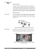
Figure 8. Front Panel Removal
5. Snap the front panel onto the Auxiliary Mounting Plate in the same
way it was attached to the main radio chassis.
6. Mount the Auxiliary Mounting Plate to the rack cabinet at any con-
venient location within the range of the 7-foot cable
(P/N 03-2198A04) supplied in the kit.
7. Attach the extension cable between the front panel modular connec-
tor and the in-line splice connector on the radio chassis.
4.3 Primary Power
The radio can be powered from a variety of standard AC and DC power
sources ranging between 15 and 125 Vdc, and 115/230 Vac. The nom-
inal input voltage is marked on the module at the rear of the radio or
external power supply unit. Please see “Technical Specifications” on
Page 93 for allowable voltage ranges.
Before connecting a primary power source to the radio, verify
the source voltage matches the power supply’s operating range
and type of service (AC or DC). Improper voltages (contin-
uous or transient) may damage the equipment.
Redundant units will have two identical internal or external power sup-
plies depending on the option chosen at the time the order was placed.
Non-redundant units will have only one internal or external power
supply. The 15 Vdc models have a interface panel and switch on the
chassis, but no internal supply.
A
CAUTION
POSSIBLE
EQUIPMENT
DAMAGE