
Specifications


16 MDS 4790/9790 Series I/O Guide MDS 05-3438A01, Rev. E
Low-Voltage Disconnect Feature
The Battery Control Board contains a Low-Voltage Disconnect circuit.
It prevents damage that may be caused when the backup battery drops
below 10.65 volts—such as during an extended AC power outage.
When the back-up battery voltage drops to 10.65 Volts (± 0.2 V), the
Low-Voltage Disconnect assembly automatically disconnects the bat-
tery from the radio. This stops operation of the radio and protects the
battery from potential damage. When AC power returns, the battery is
automatically connected to the power supply for re-charging and the
radio resumes normal operation.
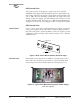
Battery Reset Switch (SW1/LVD PCB)
Normally, the operation of the Low-Voltage Disconnect assembly is
fully-automatic. The only exception is when replacing a discharged bat-
tery with a charged battery when AC power is not present. In this case,
it is necessary to press the
BATTERY RESET SWITCH, SW1 on the Battery
Control Board, after installing the new battery. (See Figure 12.) Use a
pen or other pointed object to press the switch. This will enable the radio
to operate until the new battery is discharged or the AC power is
restored.
Figure 12. Location of Battery Reset Switch
NOTE: For replacement of a backup battery, refer to “Installation &
Removal of Backup Battery (P/N 28-1575Axx)” on Page 83.
4.5 Antenna Installation
The antenna manufacturer’s installation instructions should be followed
for proper operation of the antenna. Using the proper mounting hard-
ware and bracket ensures a secure mounting arrangement with no pat-
tern distortion or detuning of the antenna.
Battery Reset Switch
(See Text)
Duplexer