
Specifications


MDS 05-3438A01, Rev. E MDS 4790/9790 Series I/O Guide 17
Regardless of the antenna make, mount the antenna in the clear, as far
away as possible from obstructions such as buildings, metal objects and
dense foliage. Choose a location that provides a clear path in the direc-
tion of the associated stations.
NOTE: Strong fields near the antenna can interfere with the operation
of low-level circuits and change the values of the data being
received. For this reason, the antenna should be mounted at
least 10 feet (3 meters) from the radio and other electronic
equipment.
Feedline Installation
A low-loss feedline is recommended for use with the radio. See
“Antenna and Feedline Selection” on Page 8 for suggestions on
choosing the correct feedline for your installation. Whatever cable is
used, it should be kept as short as possible to keep signal losses to a min-
imum.
When installing the feedline, take care not to kink, twist or stretch the
cable. After installation, fasten the cable securely to the antenna tower
or other supporting structure.
A Type-N connector is required to connect the feedline to the radio. The
feedline connectors must be installed in accordance with the manufac-
turer’s instructions. Follow the manufacturer’s recommendations for
weatherproofing connectors that will be installed outdoors.
If large-diameter, semi-rigid coaxial cable is used for the feedline, insert
a short length of 1/4 inch Superflex
TM
Cable (MDS P/N 97-1677A28) or
other low-loss flexible cable between the radio and the feedline. This
flexible interface eliminates tight bends in the feedline and reduces
stresses on the feedline and connectors. The flexible section also allows
the radio to be mounted on slides and pulled out without placing undue
stress on the transmission line.
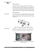
4.6 Interface Wiring Connections
All connections to the master station are made at the rear panel. (See
Figure 13 below.) Refer to the following descriptions for specific infor-
mation on these connections.