
Specifications


20 MDS 4790/9790 Series I/O Guide MDS 05-3438A01, Rev. E
Invisible place holder
Figure 17. Coaxial Connectors for Older Radios
(For units intended to operate with an external duplexer)
Invisible place holder
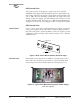
Figure 18. RF Interconnections for Older Units
(For units intended to operate with
External Duplexer and/or Cavity Filter)
Ground Connection
A chassis grounding screw is located on the plate directly above the
coaxial connectors. Use this screw to connect the chassis to an Earth
(safety) ground, or other suitable grounding bus for the communications
system. The ground lead should be kept as short as possible.
Connect all rack equipment and associated hardware grounds to the
building’s ground system at the breaker panel for the primary power.
The objective is to create a single-point ground system.
Do not overlook providing a good ground connection for the equipment
attached to the
DATA PORT to prevent damage.
Finally, use lightning protectors where the antenna transmission lines
enter the building; bond them to the tower ground, if it is nearby.
OPTIONAL POWER SUPPLY
(Redundant Models)
ADDITIONAL HEATSINK
(Redundant Models)
RADIO A
RADIO B
RX in (from Duplexer) TX out (to Duplexer)
This view applies only to units shipped prior to June 1, 2000
RX
Master Station
TX
Cavity Filter
IN OUT
Ext. Duplexer
RX
TX
ANT