
Specifications


22 MDS 4790/9790 Series I/O Guide MDS 05-3438A01, Rev. E
Data Interface Connector—J3
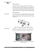
The data connector on the radio’s rear panel is the main system data
interface It typically connects to the host computer. Refer to Figure 21
and Table 4 for pinout details.
Invisible place holder
Figure 21. Data Interface Connector, J3
Table 4. Data Interface Pinout
Pin Num-
ber
Input/Output Pin Description
1— Shield Connection. Connects to ground (negative
supply potential) on the radio’s PC board.
2IN TXD—Transmitted Data. Accepts TX data from the
connected device.
3 OUT RXD—Received Data. Outputs received data to the
connected device.
4IN RTS—Request-to-Send Input. Keys the
transmitter when RTS asserted.
5 OUT CTS—Clear-to-Send Output. Active after the
programmed CTS delay time has elapsed.
6 OUT DSR—Data Set Ready. Provides a +6 Vdc DSR
signal through a 2.5 kΩ resistor.
7-- Signal Ground. Connects to ground (negative
supply potential) at radio’s PC board.
8 OUT DCD—Data Carrier Detect. Goes active when the
radio detects an on-frequency signal.
9-- No Connection
10 -- No Connection
11 OUT Receive Audio Monitoring Connection (used for
diagnostics). Drives high-impedance load.
12 -- No Connection
13 -- No Connection
14 -- No Connection
15 OUT Do not connect—Reserved for future use.
16 -- No Connection
17 -- Do not connect—Reserved for future use.
18 -- No Connection
1
13
25
14